Tried my best to make it compact and easy to understand, but clearly I failed.
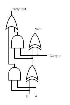
Bottom 2 switches are inputs A and B. Right most switch is the Carry In.
Top capacitor represents the Sum output. Left capacitor represents the Carry Out.
Tried my best to make it compact and easy to understand, but clearly I failed.
Bottom 2 switches are inputs A and B. Right most switch is the Carry In.
Top capacitor represents the Sum output. Left capacitor represents the Carry Out.
Simple Diagram for how it works:
Excellent first post and nicely done! What Spintronics lacks in ability for compactness and readability, it more than makes up for in style! Only qualm I have is that it looks like you’ve gone for extra credit and given us a full adder rather than a half 
Look forward to seeing when you have an 8-bit adder put together
The title is meant to say “Full Adder”, not “Half Adder”.
Whoops
i actually created a half adder with ammeters
I’ll explain why I have said expandable when I replaced your voltmeters with transistors
Actually I made a four bit adder, (it a ripple carry one) although an 8 bit adder might be too much for the simulator4-bit adder