Here are now the bit adders:
-
The Half Adder
Here the input switches A and B at the bottom and transistors represent the output (Sum on top and Carry(out) to the left) marked as S(0) and C(Out).
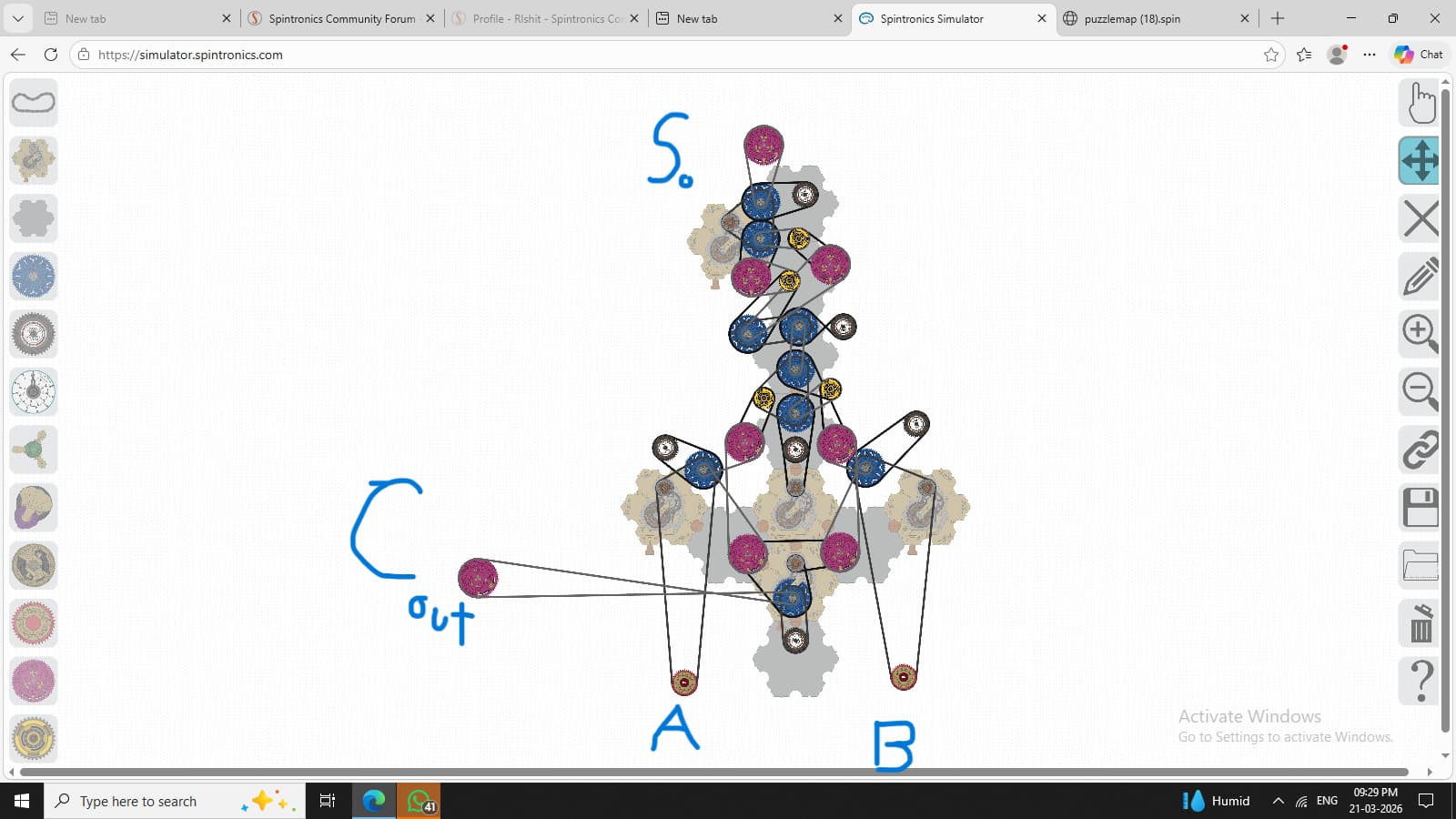
it uses and and gate at the bottom while at the top is an XOR gate. -
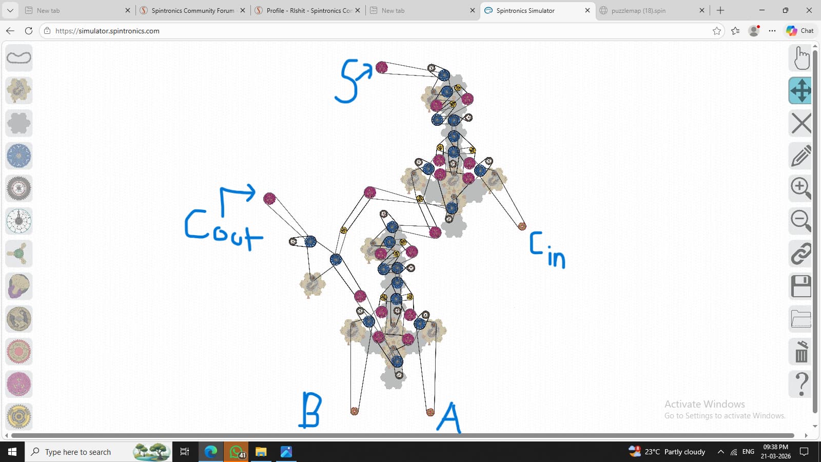
The Full Adder
Here it has two switches and a carry Switch. THe outputs are same (IN all adders the output is of transistors)
-
Two Bit Adder
Here there’s no carry
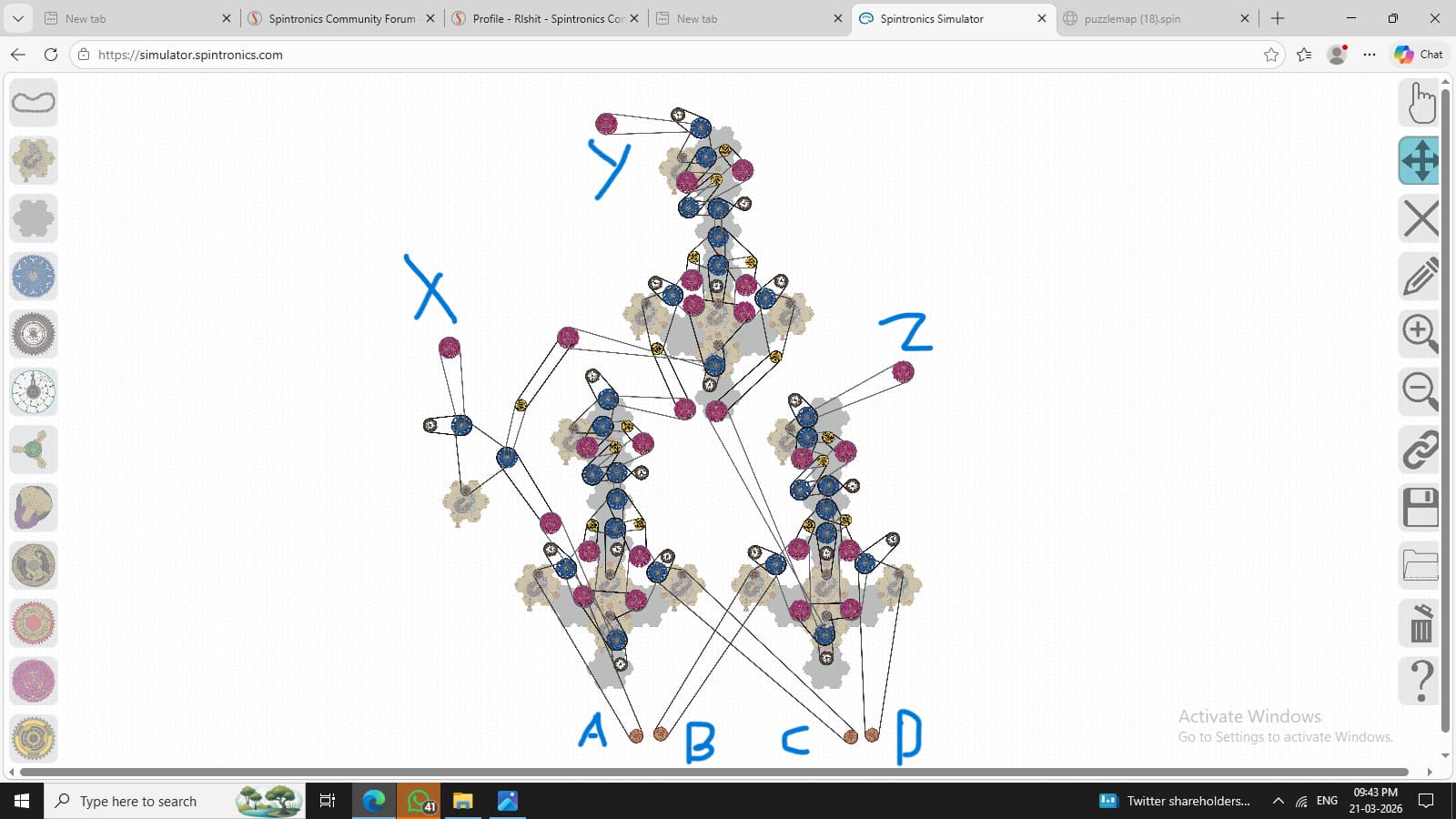
4)Three Bit Adder(No carry) (inputs and outputs at the bottom)
5)Four Bit Adder(No Carry)
6)Four Bit Adder(With Carry)
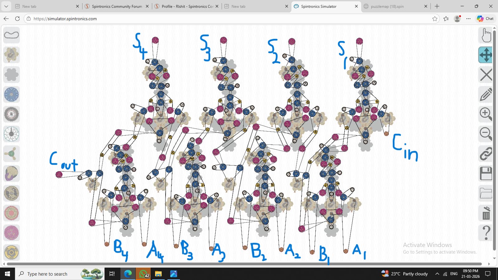
Unfortunately  I haven’t been able to build an 8-bit adder due to the simulator reaching its limits, but yes, an 8-bit adder can be built in spintronics.