When the button is off, the output through the resistor is 6V; when the button is on the output is 12V. I think this would make a good puzzle.
1 Like
That’s pretty neat! I added a Volt Meter so you could read the 6V and 12V as the button is toggled.
The layout of the circuit is special because it’s one of the few that exist in spintronics but can’t be replicated in a real electric circuit. The two diode full bridge rectifier, and the polarity button from challenge 67 are other examples of the same connectivity with different components placed in each position. I’m working on characterizing all of these special groupings based on the number of junctions needed. With 1 junction there is just the voltage doubler/halver, and layout used for the circuits mentioned above is the only one that exists for 2 junctions.
1 Like
Cool circuit! Nice use of the diode. Excited to see what the rest of your characterization work yields.
1 Like
I think a junction centric model of circuits is useful because without junctions everything is in series. The fundamental structure of any circuit can be described in terms of junctions and what I’m going to coin as terminals. Each terminal can contain an unlimited number of components, but all the components at a single terminal are in series with one another.
Because each junction can connect to at most 3 separate things, the maximum number of terminals is 3J. However, with 3J terminals we would just have a bunch of disjointed parallel circuits. If we impose the condition that a single circuit be entirely interconnected, we need to fuse terminals together until there are at most 2J+1 terminals.
However, with 2J+1 terminals, the structure is always tree like, with branches but no closed loops. These types of circuits don’t have any abnormal behavior, and always mirror electric circuits. So, we need to reduce the upper limit to 2J terminals to create at least 1 closed loop somewhere in the circuit. For example, my circuit (as well as the full bridge rectifier and the polarity button from challenge 67) has 2 junctions and 4 terminals. This also proves by counterexample that the upper limit on terminals in a member of the set of special circuits can’t be lower than 2J.
Here’s the 2J 4T circuit as a graph.
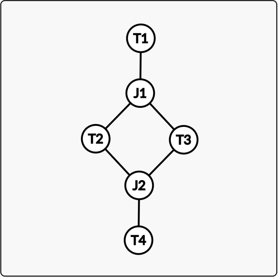
I think the simplest case to analyze is the set of circuits where every terminal is connected to at most 2 junctions, and every junction is connected to 3 different terminals. The other cases are definitely very important, but they’re much tricker. The above circuit is a member of this simple case.
However, this representation of the circuit as a graph doesn’t actually fully characterize it. There is a version that displays normal behavior (where if we take T1 to be the power source, T2 and T3 are in parallel with one another but both are in series with T4) and one with special behavior. The way to tell is to immobilize T1 and T4, and to test if the terminals in the loop are still free to spin. In the case of the normal circuit, they can spin freely. In the case of the special circuit, they become locked.
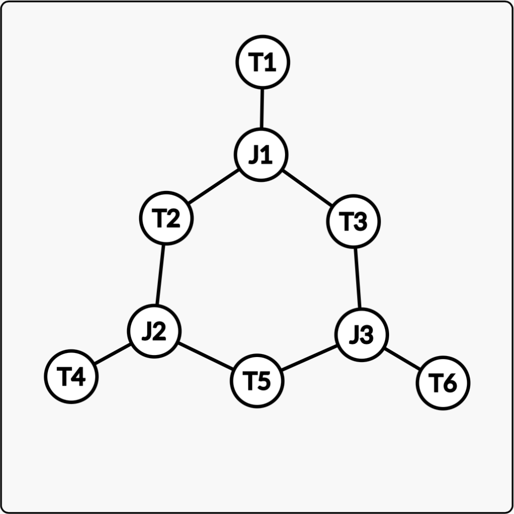
From this we can create a simple infinite series of special circuits with 2J terminals by expanding the size of the loop. Here’s the second one in the series. Again, the key feature that differentiates it from the normal circuit is that if T1, T4, and T6 are immobilized, the remaining terminals are not free to spin.
It turns out there are actually 2 ways to wire a full bridge rectifier. I had been doing it this way which I think is more intuitive.
However, it actually seems to work better in the simulator if you wire it this way. You can see there’s almost no lag between the input and output, unlike with the first layout.
In the first circuit the diodes spin at the same speed as the input and output, but interestingly, in the second setup the diodes actually spin twice as fast as the input and output.
1 Like
I’m trying to use an approach involving degrees of freedom to establish limits on the number of terminals with respect to the number of junctions in general, not just for the special spintronics circuits. For generality sake this assumes that every terminal is just a resistor or a switch, because things like diodes can constrain degrees of freedom as well in complicated ways, and top and bottom sprockets of a transistor are usually two different terminals, which is an exception among all the parts.
Every terminal adds one degree of freedom. In general a gear has one degree of freedom because it is pinned to the ground and can only rotate. So we can imagine that 5 resistors or switches sitting with no chain connecting any of them clearly have 5 degrees of freedom because they can all rotate independently.
Connecting two terminals with chain (usually, unless the constraint is redundant) reduces the degrees of freedom by one, however according to my definition of terminal, if two terminals are directly connected, they cease to be two terminals and instead become one terminal.
So the only way to reduce the degrees of freedom of some number of terminals (assuming that every terminal is otherwise free to move as a resistor and not a diode or transistor) is to add junctions. Every junction usually removes 1 degree of freedom. An example of this would be 3 resistors or switches. With no constraint they have 3 degrees of freedom. If we add a junction connecting all 3, the total number of degrees of freedom is two. The number of degrees of freedom can be experimentally validated. Immobilizing a terminal via switch reduces the total number of degrees of freedom by 1 (unless the terminal already couldn’t move to begin with). So we can simply start freezing terminals until nothing can move, indicating that there are 0 degrees of freedom. In the case of 3 resistors connected to a junction, of 1 of the resistors is frozen, the other 2 are now locked together, indicating 1 degree of freedom, and if 2 resistors are frozen, the remaining one cannot move at all, indicating 0 degrees of freedom.
I’m 99.9% sure that the number of degrees of freedom can never be lower than terminals minus junctions T-J. However it can be higher. The simplest example is 3 terminals where each terminal is connected to 2 junctions. If all the polarities match, the second junction isn’t applying any additional constraint past what the first one is, so the system still has 2 degrees of freedom. If the polarities are mismatched, one the the resistors is permanently frozen, and the other two are locked to each other, for a total of 1 degree of freedom.
My current conjecture is that if a system is over constrained (degrees of freedom is greater than T-J, at least one of the junctions can be deleted without changing the theoretical properties of the system. If this is true it would make analyzing circuits a lot easier.