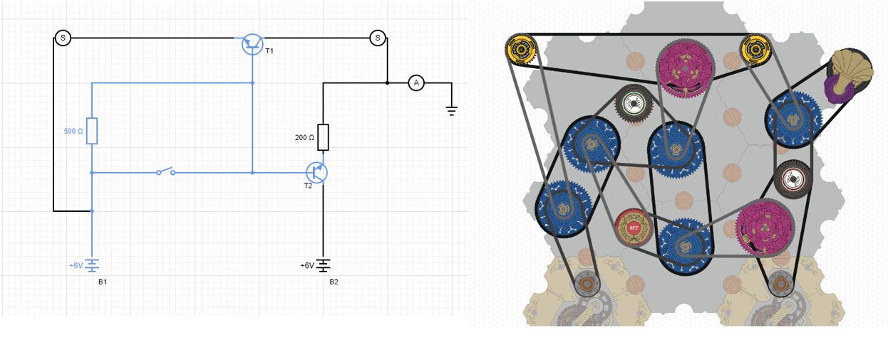
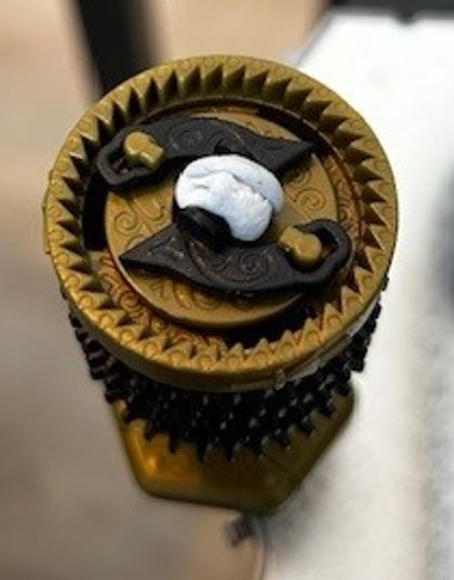
Using my crappy circuit from P6 I then faced more of a real estate problem as my T1 was way over the other side, diagonally opposite B1. So I had to go around the back which I did with 2 switches marked as S in the circuit diagram. Since there are not enough switches in the kit I used instead two level changers in the simulator. For the real HW I modified a diode to become a handy level changer. Just remove the spring and clamp the two teeth together with some gum or similar.
1 Like