In other words: can you make the circuit diagram shown in 29 with real wires and stuff using only one junction, or is being able to do that a facet of Spintronics specifically?
My guess is it is a spintronics thing.
One spintronics junction correspond to 2 electronic junctions, 1 to split the circuit and one to come back together.
In challenge 25 to 28 this coming back junction isn’t drawn.
In challenge 29 we see both junctions. When you assume the identical circuit where the 200 ohm resistor was drawn to the left of the split, two grounds would have been drawn instead of a junction and ground.
The comment on the challenge page says “of course I could make it with two junctions…”
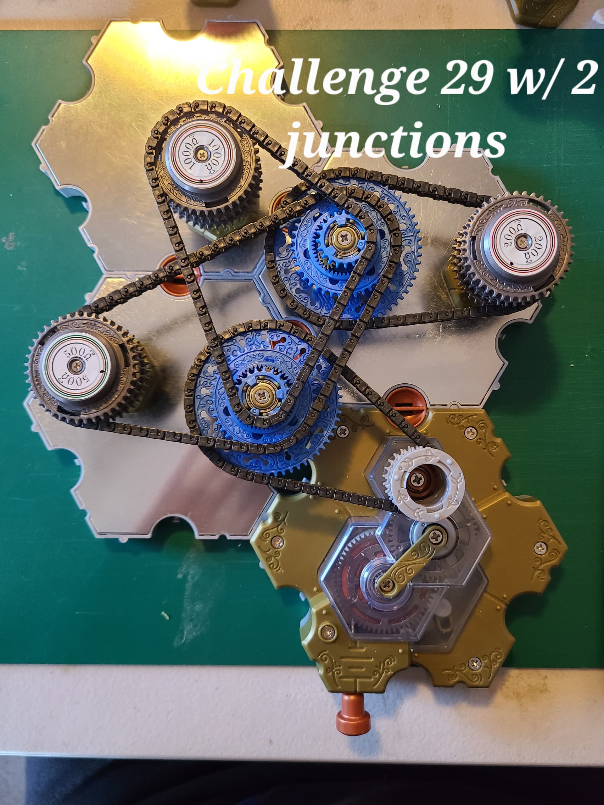
How would you actually do that using 2 ST junctions? I’ve attached a photo of my attempt, but I wanted to convince myself that this was truly equivalent to the 1 junction solution. I assumed that if the current through each of the resistors is the same for each solution then they must be equivalent, and to do this I measured the rate of spin for each.
The measurements I got are quite different (as well as the ratios). Is my circuit not equivalent, or is my experimental method flawed? Obviously the spin rate depends on the tension in the chain as well as the resistance on the resistor and also the battery repeatability, but I repeated this a few times while adjusting the chain tension, yet the results for each are just too different to conclude the circuits are equivalent by this method.
This raises the larger question, is it possible to prove two different circuit arrangements are equivalent using SpinTronics?
1 Like