Hello!
I took a few hours today getting to know the simulator and I built a full adder. It’s a bit janky and probably uses some components in somewhat unintended ways, but it works.
Since I managed to delete the entire circuit before saving it (the simulator seems to not handle the screen being resized terribly well), I only have a screenshot of it, unfortunately. At some point I’ll rebuild it, but for now this will have to do:
Edit: I rebuilt it!
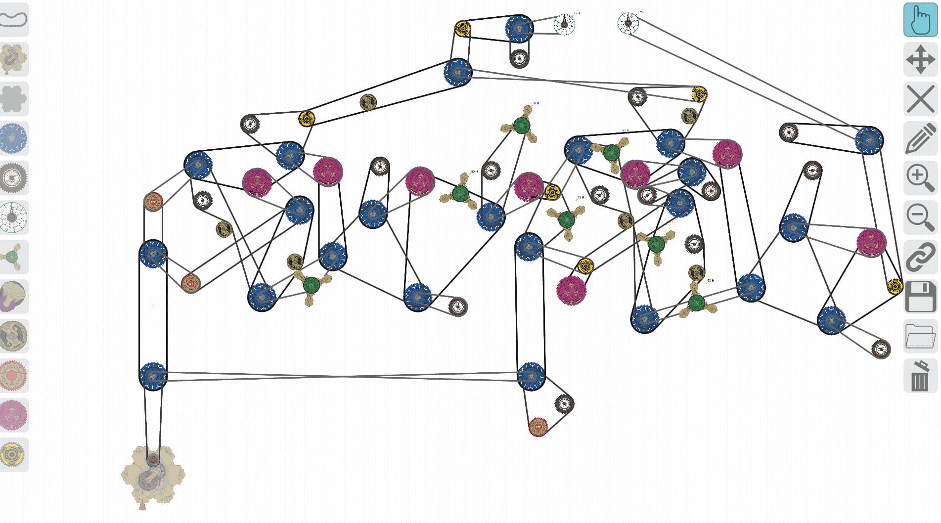
It can roughly be divided up into two sections, each of which is a half adder. The one on the right has additional “”“circuits”"" to handle taking input via transistors, but it’s fundamentally the same design.
The simulator does seem to have problems with unexpected oscillations in some situations (that’s what a lot of the seemingly superfluous components are there to deal with), as well as “”“current leakage”"" through transistors, but I was able to get this circuit to add one-bit numbers with carry reliably.
I don’t think I have it in me to build a working computer, but this demonstrates that it’s possible in theory.
Wow cool! Thanks for posting this! I’m not sure I understand how to use it. I imagine all the switches go in the ON state, but then how do you toggle it?
Well, it’s a one-bit full adder, so you can’t do anything massively exciting with just this on its own (you would need to build two of these and connect them for a two-bit adder and eight to be able to add bytes), but you input the states of the two bits you want to add using the two switches, and then you input the carry signal from the previous (non-existent) adder using the transistor in the bottom middle that looks like it’s not attached to anything. The two capacitors on the top give the output - carry out on the left and signal out on the right.
try to copy and paste the circuit and connect two adders together 
this is a problem copy and pasting circuits is not allowed in the simulator