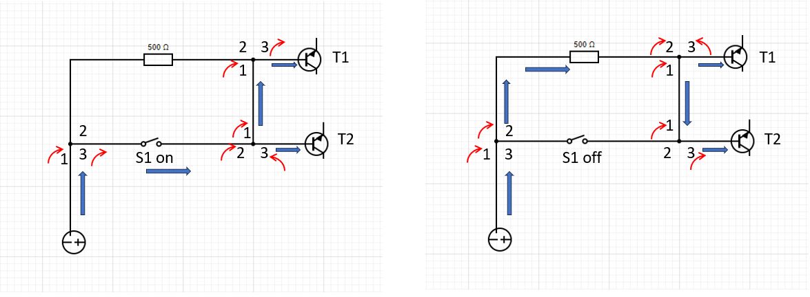
I arrived at a similar circuit to the published solution. I found it easier to sketch out the rotations at the junctions to help picture which direction they need to rotate. On the LHS the current the bottom path as S1 is ON. On the RHS the current follows the top path as S1 is OFF.