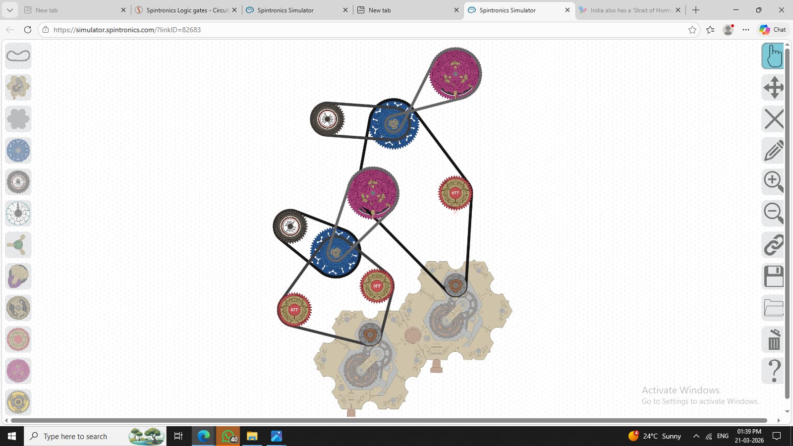
Hello everyone! Here are some logic gates I built
-
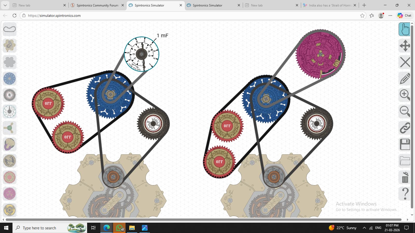
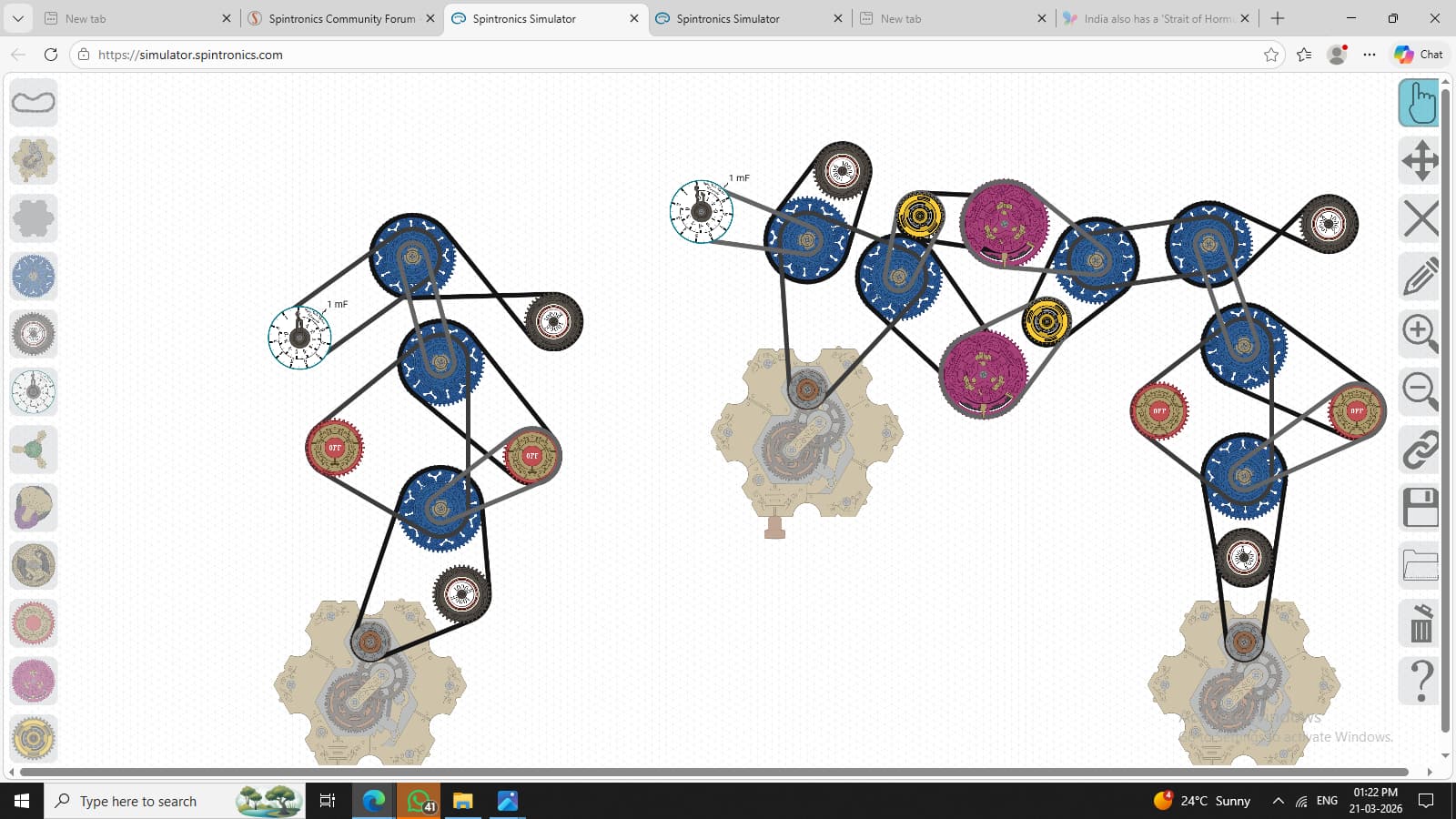
Identity Gate(pretty boring but this is the basic structure of what I use for Spintronics gates)
Switch is series in output -
Not Gate
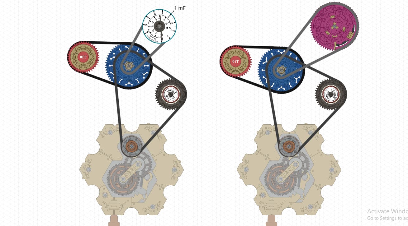
Switch is parallel in output -
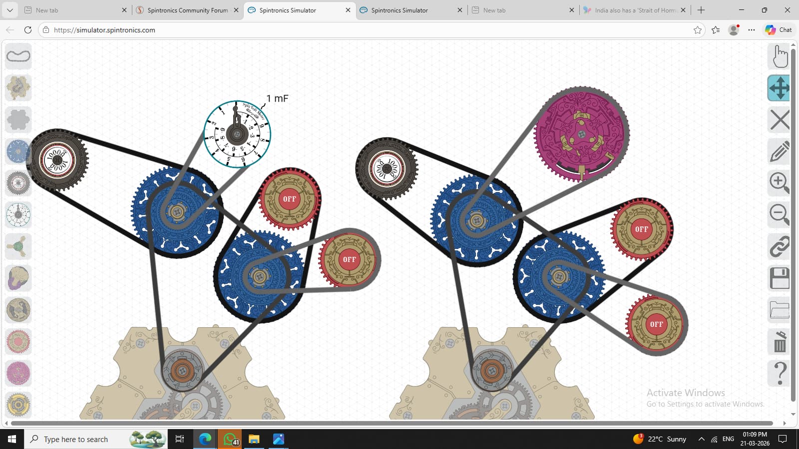
AND Gate
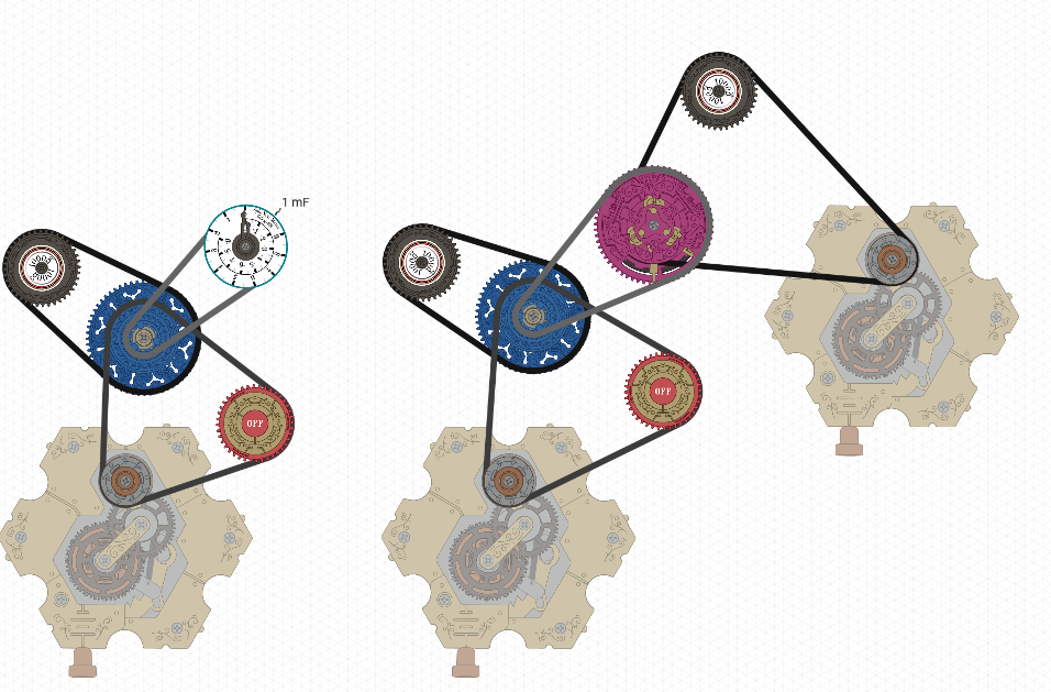
Two switches and voltmeter in series -
NAND Gate
two switches in series and voltmeter in parallel -
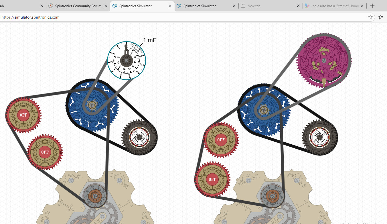
OR Gate
two switches in parallel, series with voltmeter -
NOR Gate
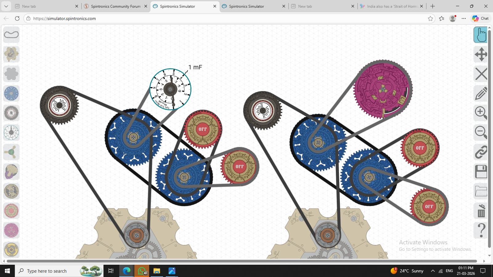
two switches and voltmeter in parallel -
XOR Gate There are two versions:
7.1)XOR Gate 1
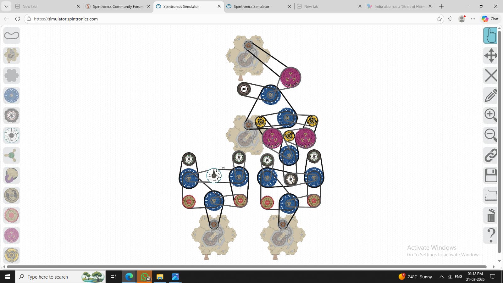
7.2)XOR Gate 2
here a Wheatstone bridge configuration is achieved
if you see, there are two circuit versions, in most logic gates, where on one voltmeter is output, the other which has transistor as output. the transistor version is expandable; it can be used to connect through other logic gates by making the transistor as a new switch.