One of the difficulties in posing challenges and especially (as I’ve found) designing challenges from scratch is coming up with the proposed function, as well as figuring out if a circuit with such function is possible to construct. In working on these problems myself, I created a notation to precisely describe the behavior of a spintronics circuit.
Since all of the components in spintronics are linear (the transistor is a bit problematic here, but if we consider the two terminals as separate components this technique can still be applied), the behavior of any spintronic circuit can be described by a system of linear equations, or more succinctly as a matrix. There are several benefits of this. Firstly, we can describe a circuit’s behavior without yet knowing how to build it. More valuable that that, we can use elementary matrix operations to modify the matrix and infer additional information about the circuit, still without having built it.
I’ll demonstrate with an example:
Challenge #50
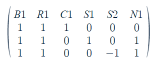
Each column is labelled with a component, and each row represents one possible mode of motion based on relative currents (I follow the convention of representing clockwise rotation with a positive coefficient and counterclockwise rotation with a negative coefficient). We can see that B1 and R1 are in series, because the ratio of their coefficients is the same across all rows (in this case, they are exactly identical, but since a row can always be multiplied or divided by a constant, it’s the ratio that is important). We can also understand the key behaviors of the circuit by looking at the matrix. For example: if the battery is spinning, and both switches are turned off, the first row tells us that the current through C1 must match the battery.
You may also be wondering what N1 is. In the solution to challenge 50, there is a chain that connects the two junctions, but does not have an additional component on it. Because that chain is free to spin, it must be counted as one of the components of the circuit.
It’s important to keep in mind that there are an infinite number of possible matrices that can be used to describe any given circuit. However, some properties of the matrix give us important information regardless. The number of rows in the (minimized) matrix tells us the total number of degrees of freedom of the circuit. The number of degrees of freedom can be thought of as the number of independent modes of motion that a circuit can exhibit, and it’s also pretty easy to calculate. It’s simply the number of independently moving parts (including chains between junctions) minus the number of junctions. In the case of the example above, the number of independently moving parts is 5, because B1 and R1 are in series and thus only count as 1 part. In general, the more degrees of freedom a circuit has, the more difficult it is to characterize how it will behave.
It’s also important to note that this kind of analysis doesn’t tell us a lot about the actual ratio of speeds in cases where the relative motion is not fully constrained. In cases like that, the relative speed is determined by things like relative resistance, but as you can see, what component actually lies at each point is not considered at all. In the case of challenge 50, the matrix shows that when the battery spins, C1, S1, or S2, or any linear combination of them may spin along with it. The practical behavior of the circuit, ie the capacitor reading zero when either switch is on, is a result of the components themselves. Since capacitors rapidly become more difficult to turn as you apply a current to them, if either switch is open, the circuit will preferentially engage in that mode of motion rather than the one described by the first row. To make this even more clear, we can perform a couple of matrix operations on our original matrix to reframe the modes of motion and make it more clear. By subtracting row 1 from rows 2 and 3, we get:
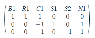
The first row of the matrix still shows how C1 is charged by the battery, but now the second and third rows show how the C1 can discharge into S1 or S2 through N1 if either switch is open.
The broad take away here is that if you were given the first matrix, you could deduce the behavior described by the second matrix just by doing row operations, without ever looking at the circuit. If you’re a person who likes designing spintronics challenges, writing a matrix like this can give you a lot of information about how such a circuit would need to behave before you’ve even figured out how to build it or if it can be built at all.