Spintronics Community Forum

The Usage of the Capacitor as a Voltmeter

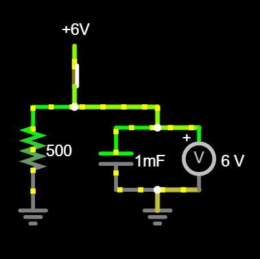
Hello! I’m new to both Spintronics and circuitry (as in I discovered it two days ago from a Steve Mould video), but I do feel it should explain somewhere the strangeness of how the capacitor is also a voltmeter. (I know it explains the piece takes the role of both, but it doesn’t explain the strange problems this creates)

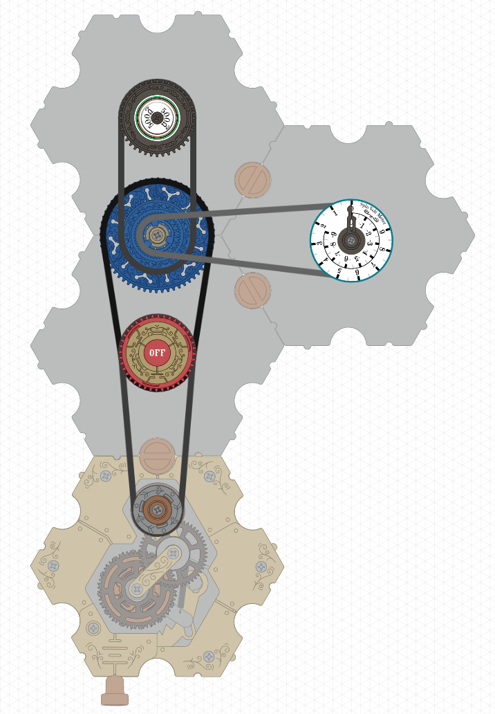
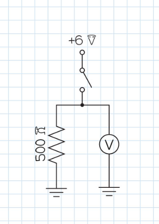
The main site shows this simple buffer gate, along with a normal circuit diagram of it.
Screenshot 2025-02-27 130515

Screenshot 2025-02-27 130605

This is all well and good, but I was pretty sure that the resistor wasn’t needed. However, when I removed it, it didn’t work correctly. I was very confused, so I ran the circuits through a normal simulator, and lo and behold: I was right. These two circuits work identically.

Screenshot 2025-02-27 130735

This is because when a capacitor is fully charged, it closes the flow of voltage, but a voltmeter lets it keep passing. And the “voltmeter” in Spintronics is also, as stated, a capacitor. I have designed a diagram below using normal circuitry to replace the Spintronics capacitor, which should hopefully explain why the resistor is needed in Spintronics, but not in traditional circuits.

Screenshot 2025-02-27 130930

The resistor on the other side is needed so that flow of voltage has another path to escape to when the capacitor closes the flow (because otherwise the voltage will stay where it is and the voltmeter won’t go down, which is the exact same scenario that plays out when you remove the resistor in the spintronics version), and a resistor is great for this as it will regulate the flow so it escapes at a consistent speed.

Also, all of this can be bypassed by using an ammeter instead of a voltmeter, but I still think a voltmeter that’s just a voltmeter with a dial could be very helpful.

(Also: is this the right topic category for this?)

This should be new parts/modifications.