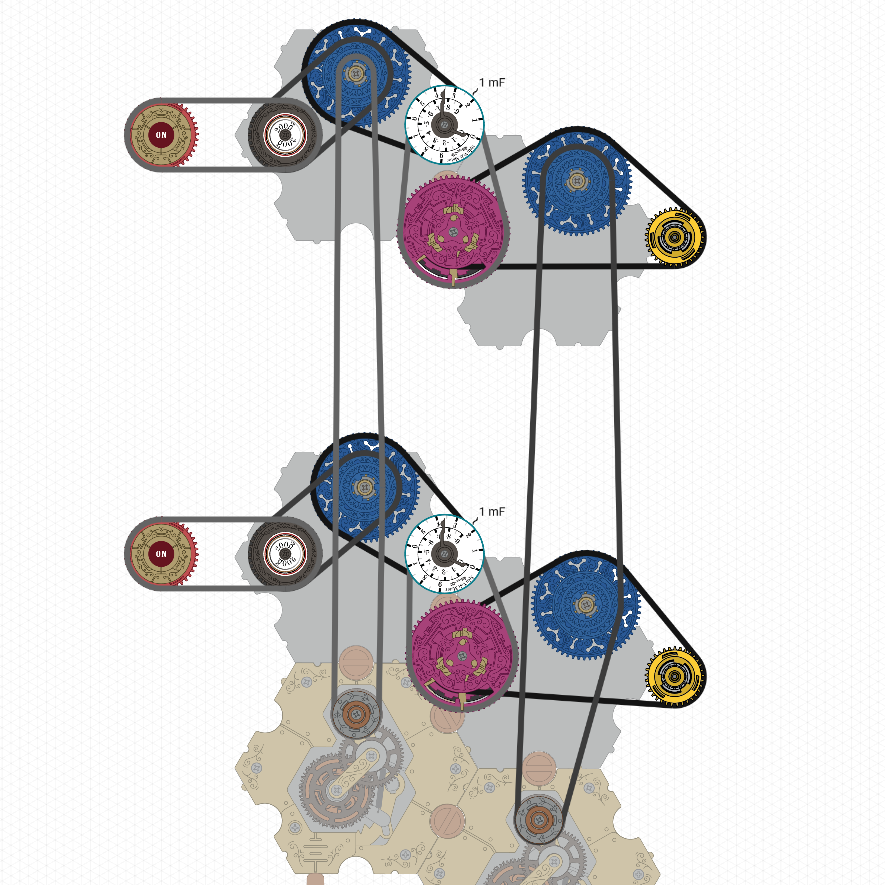
I Discovered Spintronics through a YouTube rabbit hole, and quickly came up with a way to power an arbitrary number of inputs for any circuit via only two battery components: one to provide a voltage to drive the transistor-capacitor segments on the input power bus, and another to provide current to the output bus, which can then be used by my other development: modular logic gates.
there are two issues with my design: the inputs are inverted such that having one in the on state will shut off the output, and loading in the circuit doesn’t preserve transistor state/orientation, so a really long process is needed to fix them.
In spite of this,
however, the design is extendable, modular, and easily organized.
Edit: the link to the circuit (you’ll need to follow some reset instructions to get it working, imports are bugged at the time of writing): Spintronics Simulator
To debug the circuit on import, you must follow these steps below in order.
Complete one step for all segments, then move to the next step.
-
Make sure the inputs are all in the ON state (which corresponds to an OFF output)
-
Remove the transistors.
-
Add new transistors.
-
Connect the new transistors to the capacitors. Make sure they are holding a positive voltage.
-
Alter the direction of the transistors. The voltage in the capacitors should go higher.
-
Connect the lower ring of the transistor to the ring at the corresponding point in the Output power bus. Make sure to wrap the chain around the actual output as well.