Spintronics Community Forum

Can you create arbitrary electronic circuits?

In thinking about ways to diagram spintronic circuits, it is beginning to seem to me that not every electronic circuit can be easily made with spintronic components. Specifically, can every spintronic circuit be decomposed into series-parallel pieces? That’s not true for electronic circuits, even with pure resistor circuits. That is, in finding the effective resistance of a network, sometimes you need to do more linear algebra than just the series-parallel law.

The simplest example is this one, where all edges have resistance 1 ohm except for the indicated edge which has a resistance of 2 ohms:
network
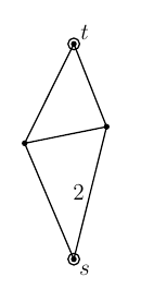
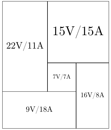
The effective resistance between the vertices marked “s” and “t” is 13/11, as elegantly proved with the following diagram:
rect-tiling
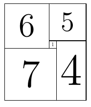
Here each rectangle has width proportional to the current flowing through a corresponding resistor, and height proportional to the voltage difference. Thus the overall current is the overall width of 11, and the overall voltage difference is 13.

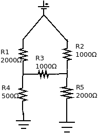
Is it possible to construct a spintronics circuit that mirrors the behaviour of that 5-resistor electronic circuit, with the effective resistance changing in the same way as the resistances vary? The first attempt I tried definitely did not work:

spintronics-ladder
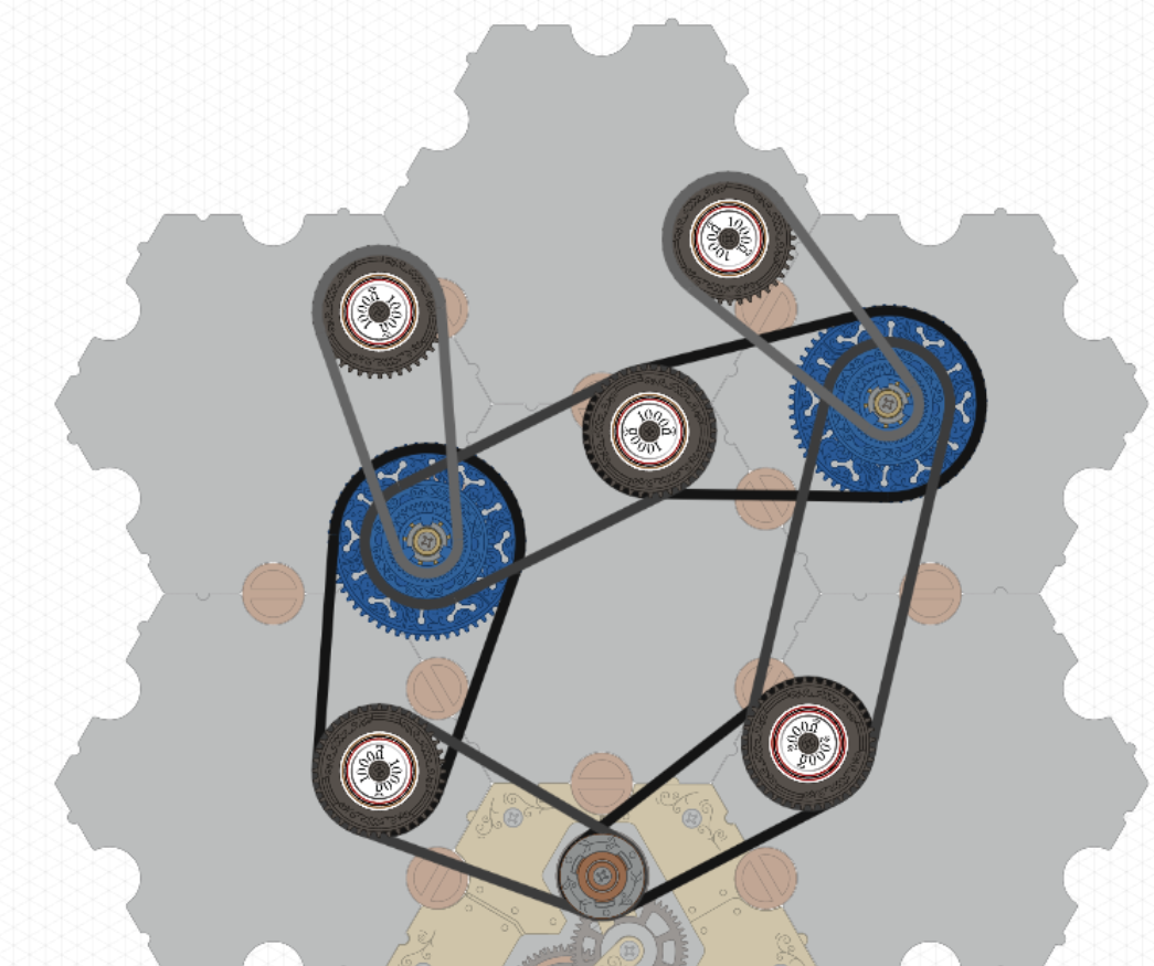
If you click on the link, you’ll see that one of the resistors (at the upper right) is rotating counterclockwise, which seems contrary to expectations.

The rotation is something you will learn later in the puzzle book (towards the end of act 1).

On the right junction, move the chain going down in the direction of the battery to the big wheel to rotate the top resistor.

Yes, I’ve been thinking hard about rotation directions in general, and I’ve read that section of the book. But indeed the circuit I posted wasn’t the one I diagrammed and intended to make as my first try; here is my initial guess:

This one agrees with the hand calculation I made, that there is no current flowing through the central resistor, despite what happens in the electrical circuit I posted initially.

My initial question remains: is there a way to produce a faithful model of that initial electrical circuit?

After a little more thought, yes, of course you can do this circuit. I tweaked the resistances to validate better that I’m really reproducing the circuit. I used these resistances:
Ladder-resistors
The solution as an electrical network is conveniently analyzed as this rectangle diagram (dividing the resistances by 1000):
ladder-rectangles
In particular, with a voltage source of 6V, the two large (2000Ω) resistors have a voltage drop of 6V22/31 ≈ 4.26V and 6V16/31 ≈ 3.10V, respectively.

You can see those voltage drops in this model:

or (in a different decomposition) here:

That exercise was useful for helping me understand what is happening and how to analyze spintronic circuits. I’ll post those thoughts separately. (For instance, there are at least two more equally valid ways to decompose the electronic circuit as a spintronic circuit.)

1 Like