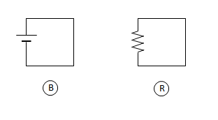
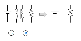
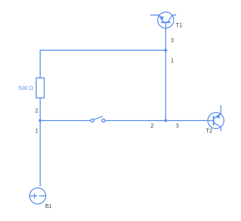
Circuit diagrams are important for both electronic and spintronic circuits. They simplify circuits to the bare essentials. It’s a lot easier to understand a circuit by looking at a diagram than by looking at a rats nest of wires or chains.
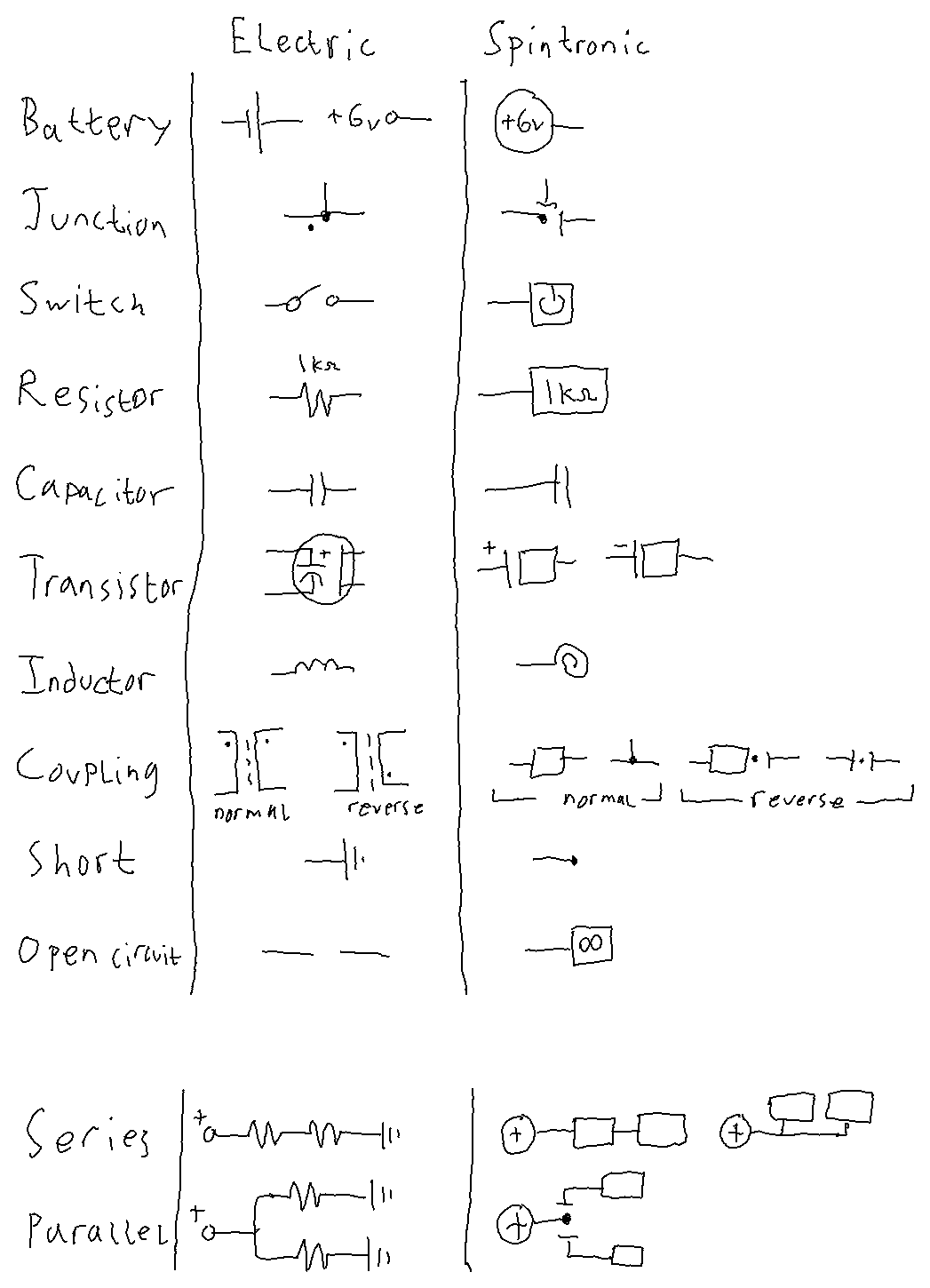
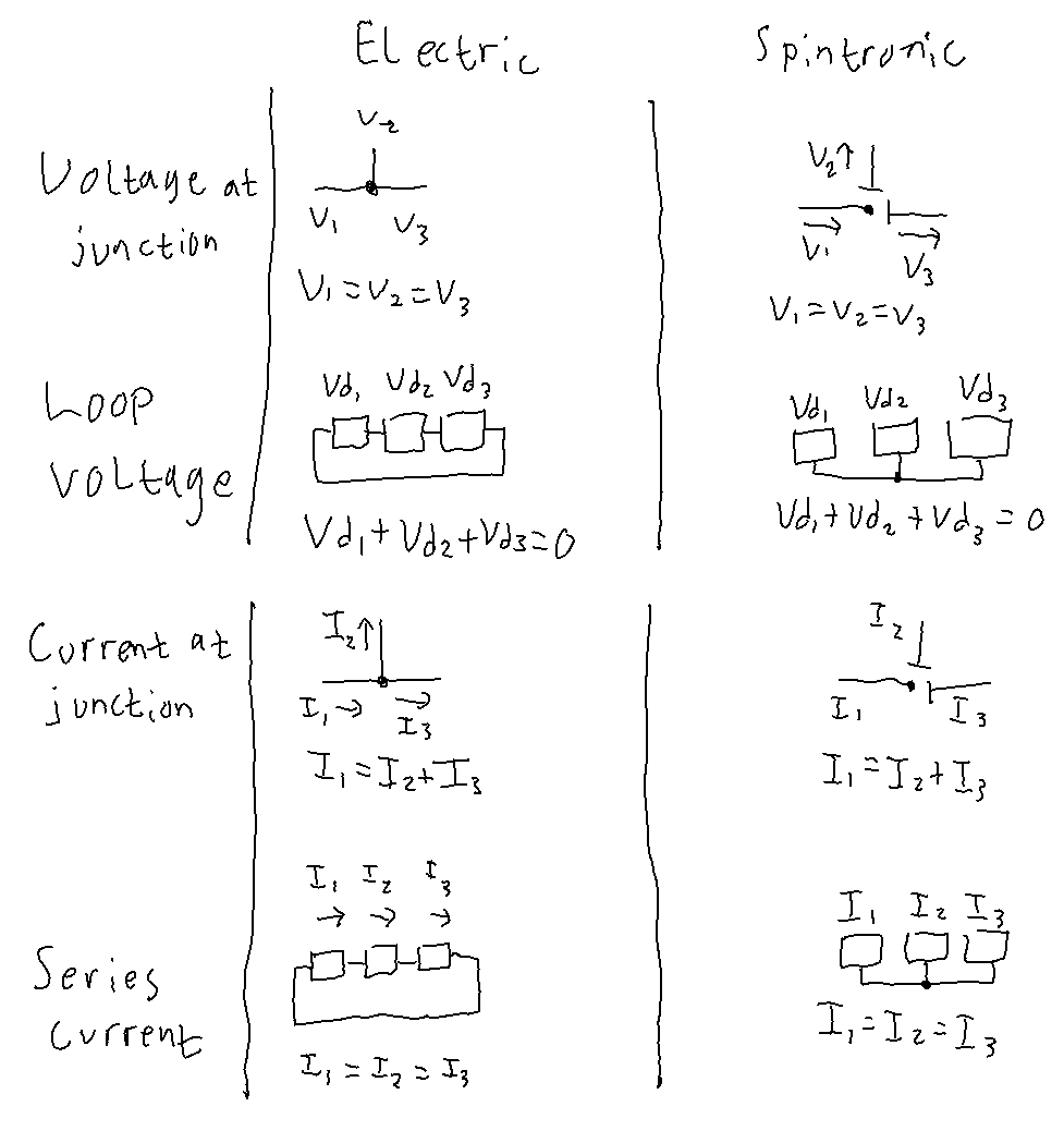
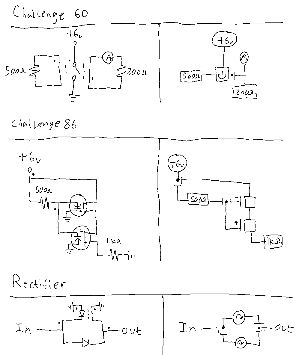
One of the main purposes of Spintronics is to teach the concepts behind electronics, so I used existing circuit diagrams and retrofitted them to work with spintronic circuits. I had to add things like junction dots and spintronic coupling to make it work. Unfortunately, it makes the circuit diagrams harder to read (which way is the current flowing in this part of the circuit, again?), and it still doesn’t offer a clear way to draw certain circuits.
Here are three situations where the circuit diagrams, as they are, are confusing:
Situation 1:
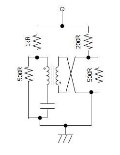
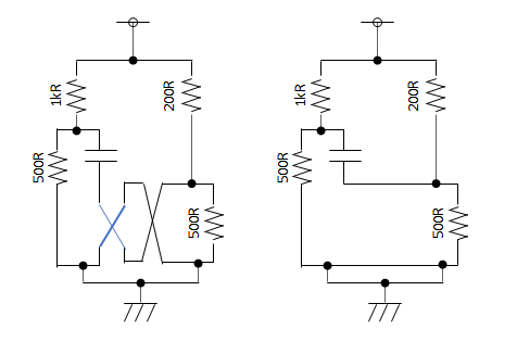
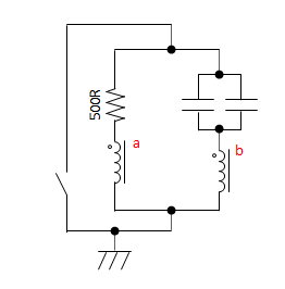
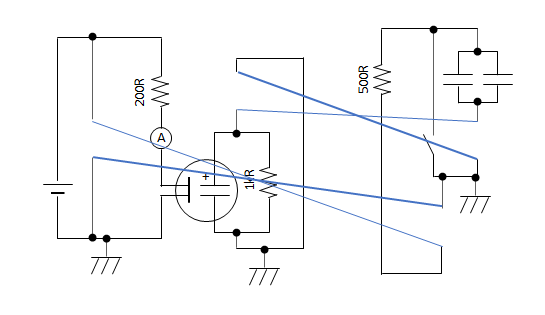
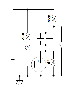
Take this circuit, for example:
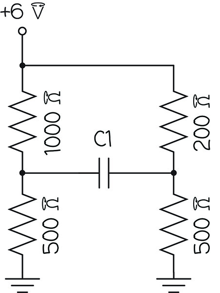
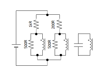
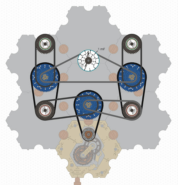
You would think that the spintronic equivalent would be this…
https://simulator.spintronics.com?linkID=470
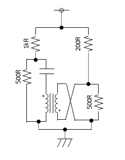
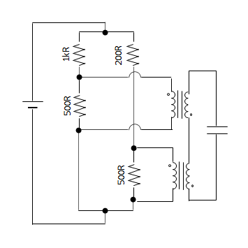
…but it’s not. In the circuit diagram, the voltages on either side of C1 fight against each other. The voltage across C1 is the difference between the voltages on either side. But in the spintronic circuit above, both voltages push clockwise, so they add to each other. C1 shows the sum of the voltages instead of the difference.
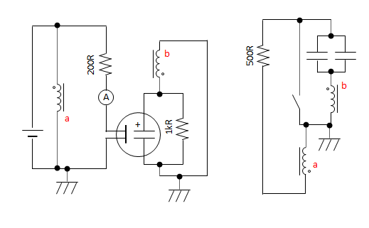
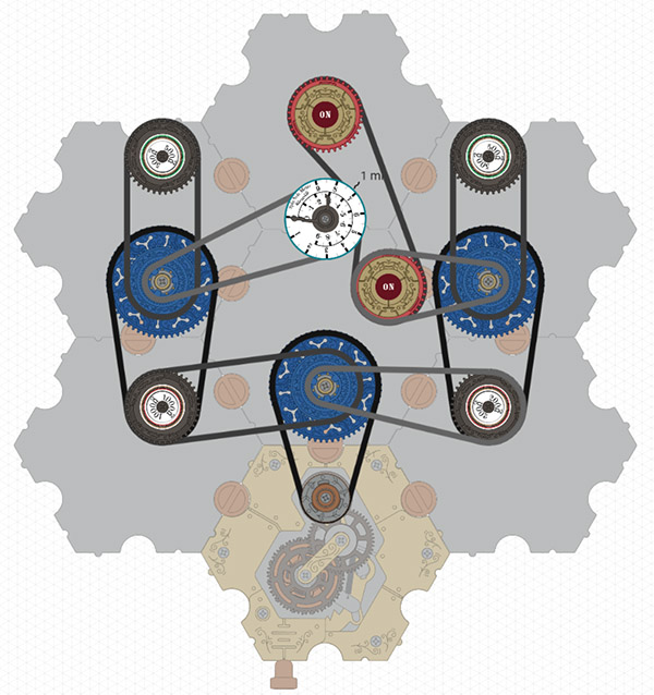
The spintronic circuit must be built differently to have the same behavior as the circuit diagram, like this:
https://simulator.spintronics.com?linkID=471
That’s certainly not intuitive.
Situation 2:
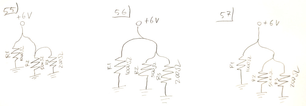
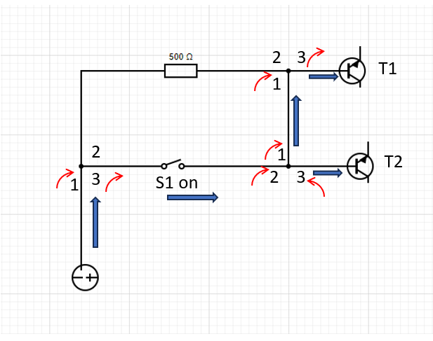
When you have a lot of junction dots in your circuit, it gets tricky to see what’s happening.
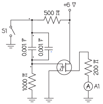
You have to trace the path of current through each junction, taking into account all of the junction dots. If it doesn’t pass by a dot, you must reverse the direction of the current, otherwise it stays the same. That makes it hard to just look at a circuit and see what’s happening. Is there a more digestible way to draw circuits that takes into account the current reversal at junctions?
Situation 3:
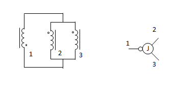
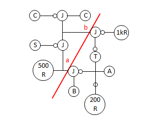
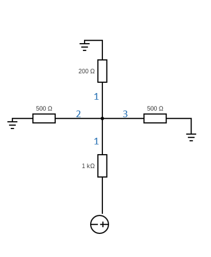
Spintronic junctions are a little more complicated than a single dot on a circuit diagram. Just like spintronic resistors and capacitors have two ‘terminals’ (i.e., where the chain enters and leaves the sprocket), each sprocket of a junction also has two terminals. Therefore, this symbol is not enough to fully describe a junction:
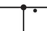
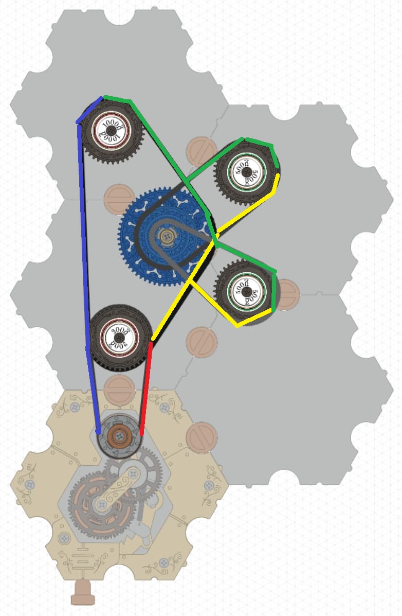
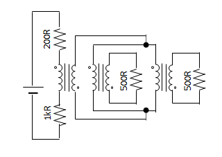
It only has three terminals! The other three terminals aren’t shown. But sometimes the other three terminals are necessary to draw. Like in this circuit:
https://simulator.spintronics.com?linkID=472
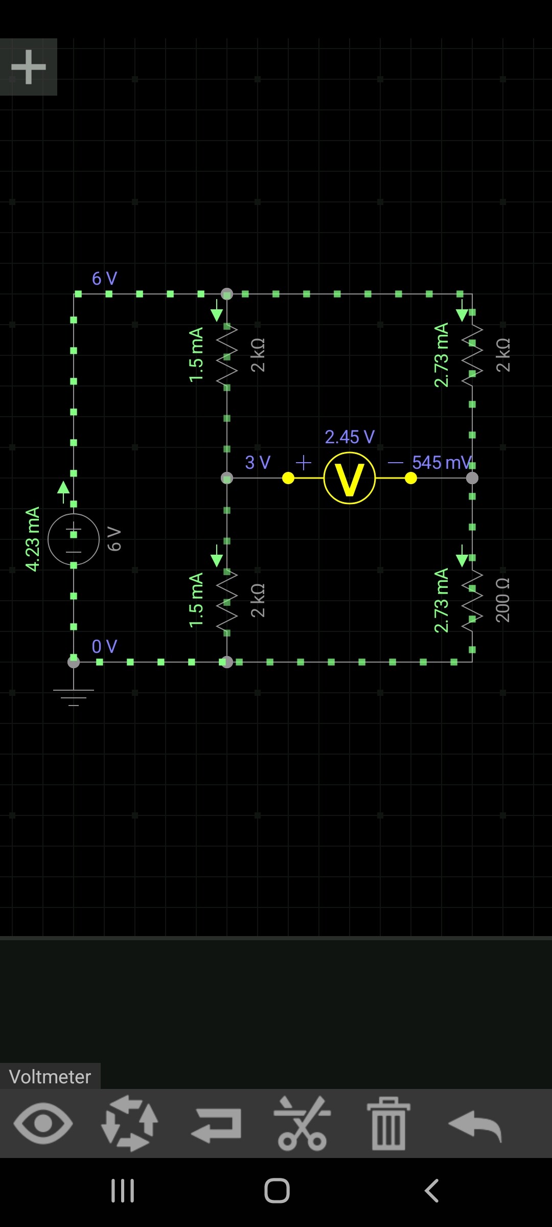
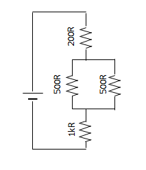
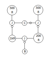
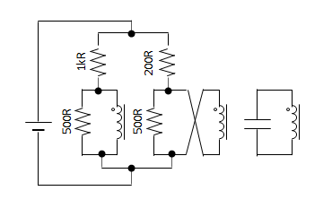
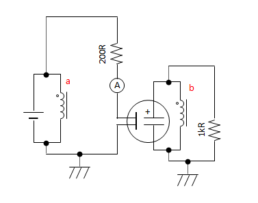
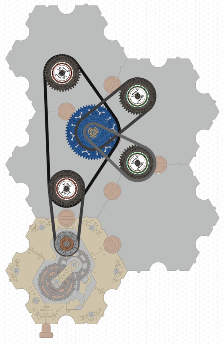
The circuit has a 200 Ω resistor, then two 500 Ω resistors in parallel, and then a 1000 Ω resistor in series. The traditional circuit diagram looks like this:
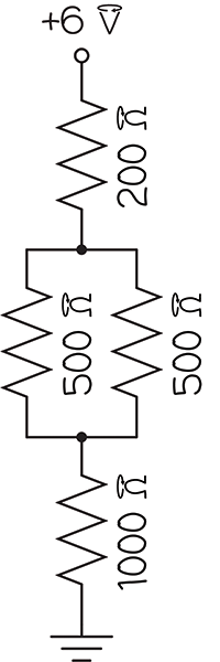
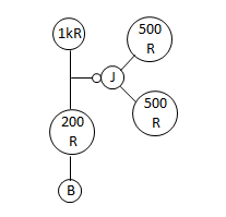
There are two junctions in the diagram, but in the spintronic circuit, there is only one junction part. That’s because the spintronic junction plays the role of both junctions in the circuit diagram. Drawn this way, you can see all 6 terminals.
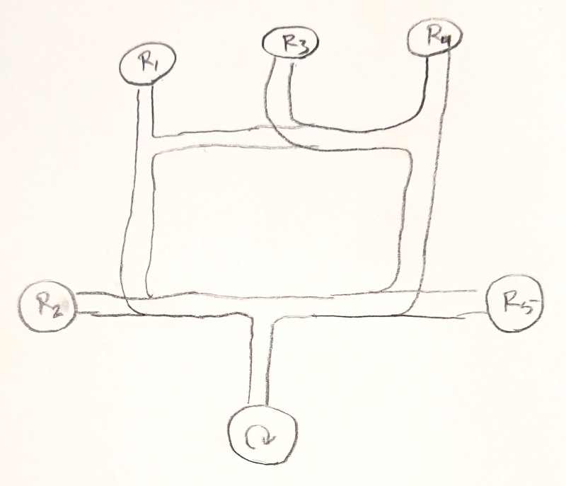
Is there a better way to show that two junctions in a circuit diagram are actually the same spintronic part?
Summary
Is there a better way to draw diagrams for spintronic circuits that is easier to read and just works for any circuit?
