Spintronics Community Forum

Is there a better way to diagram spintronic circuits?

Circuit diagrams are important for both electronic and spintronic circuits. They simplify circuits to the bare essentials. It’s a lot easier to understand a circuit by looking at a diagram than by looking at a rats nest of wires or chains.

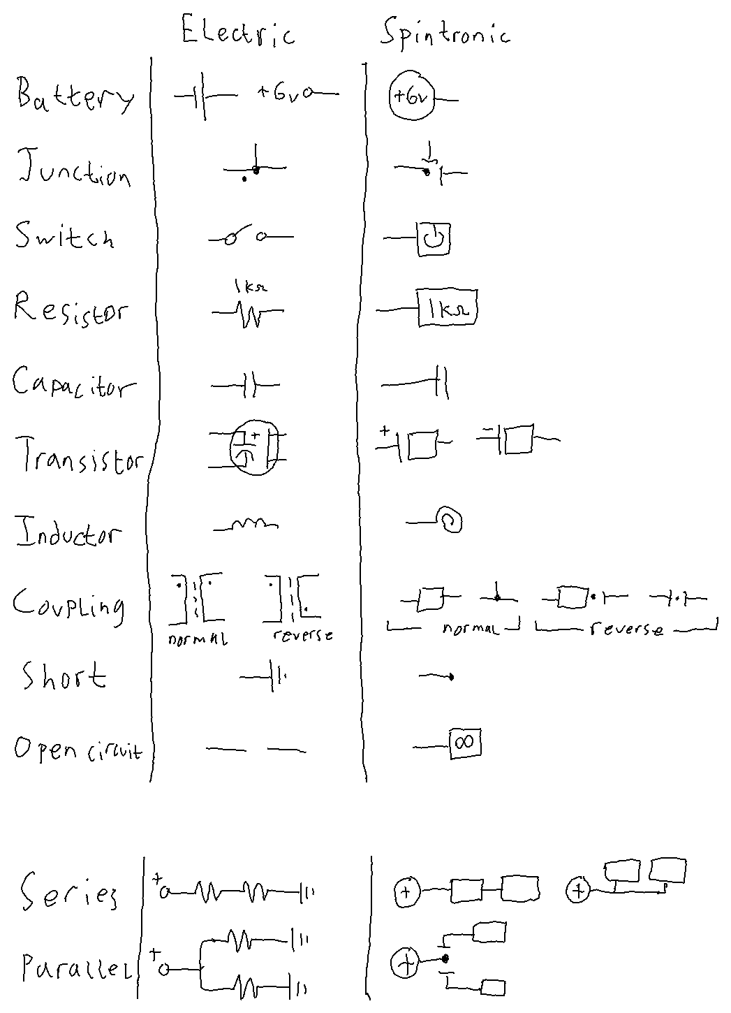
One of the main purposes of Spintronics is to teach the concepts behind electronics, so I used existing circuit diagrams and retrofitted them to work with spintronic circuits. I had to add things like junction dots and spintronic coupling to make it work. Unfortunately, it makes the circuit diagrams harder to read (which way is the current flowing in this part of the circuit, again?), and it still doesn’t offer a clear way to draw certain circuits.

Here are three situations where the circuit diagrams, as they are, are confusing:

Situation 1:

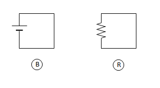
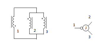
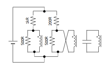
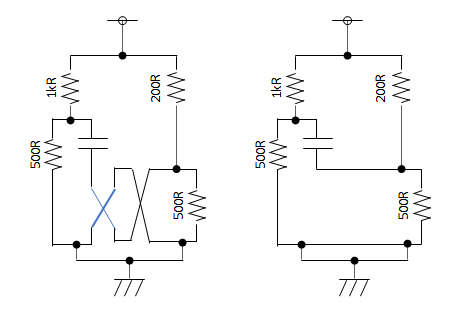
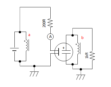
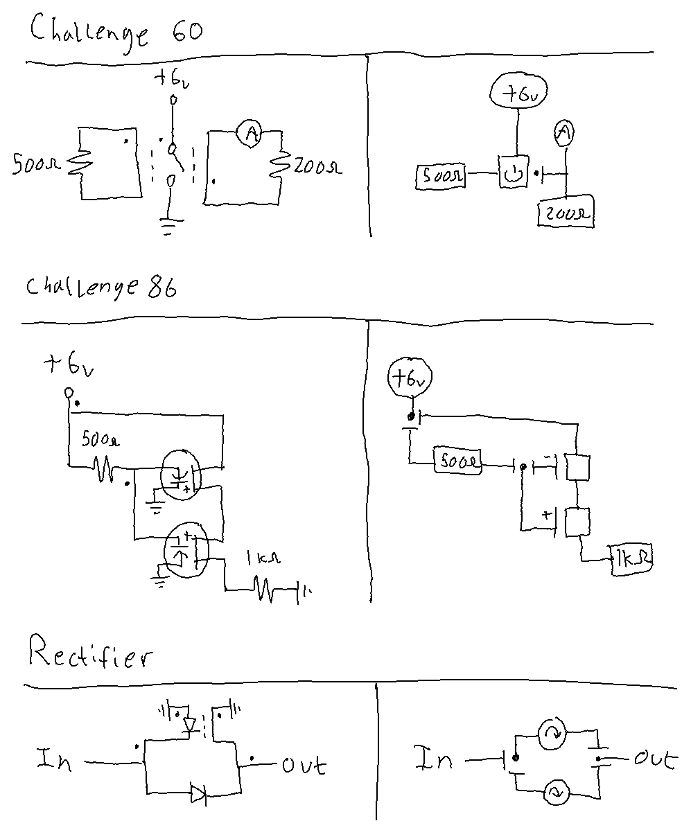
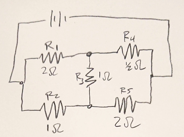
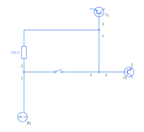
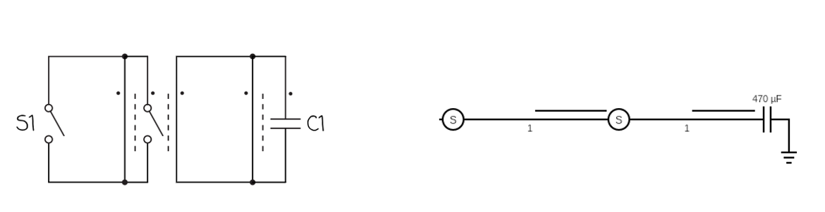
Take this circuit, for example:
circuit-diagram-problem@600x-80

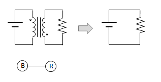
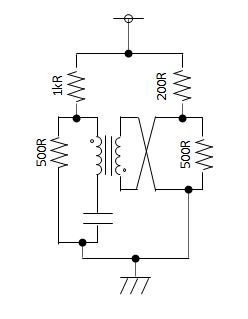
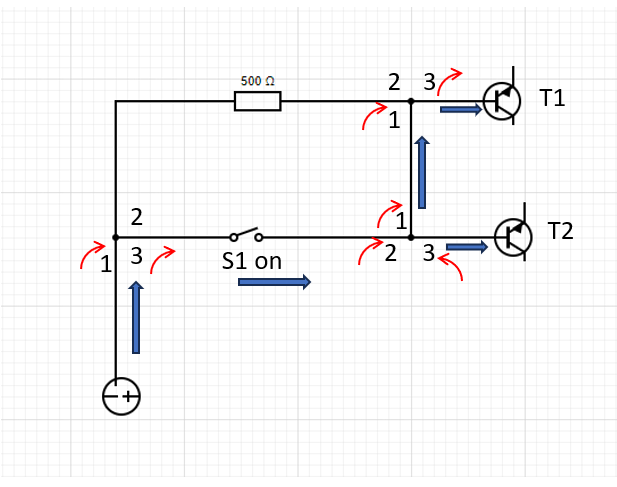
You would think that the spintronic equivalent would be this…
wrong-circuit
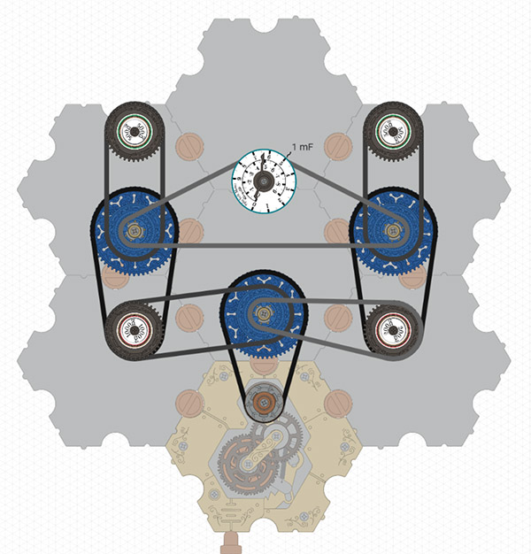
https://simulator.spintronics.com?linkID=470

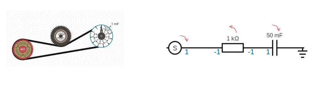
…but it’s not. In the circuit diagram, the voltages on either side of C1 fight against each other. The voltage across C1 is the difference between the voltages on either side. But in the spintronic circuit above, both voltages push clockwise, so they add to each other. C1 shows the sum of the voltages instead of the difference.

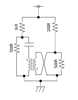
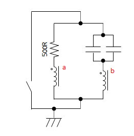
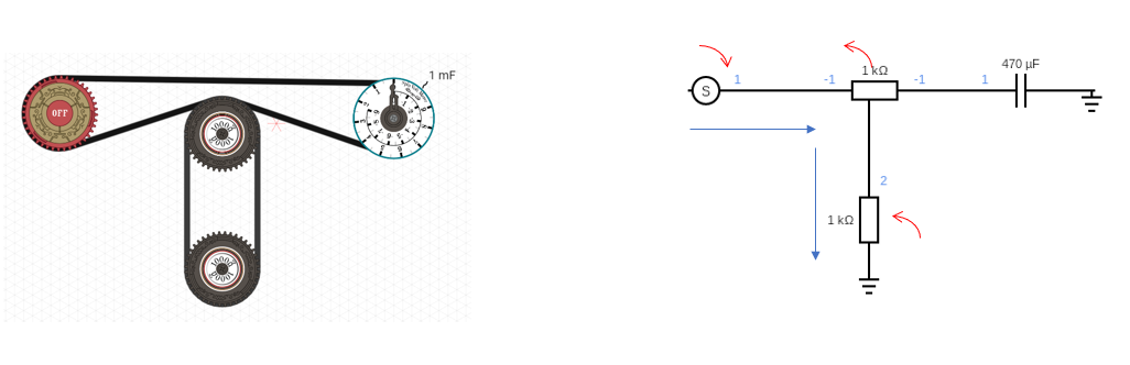
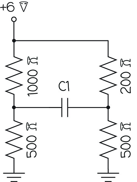
The spintronic circuit must be built differently to have the same behavior as the circuit diagram, like this:
right-circuit
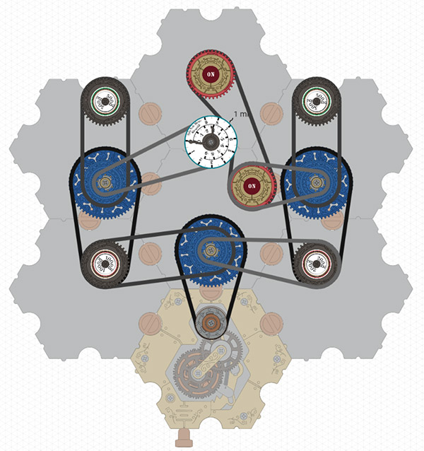
https://simulator.spintronics.com?linkID=471

That’s certainly not intuitive.

Situation 2:

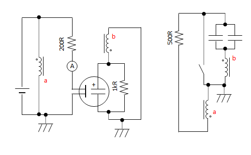
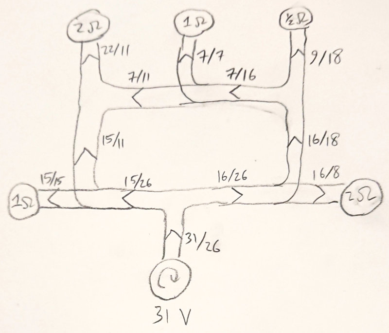
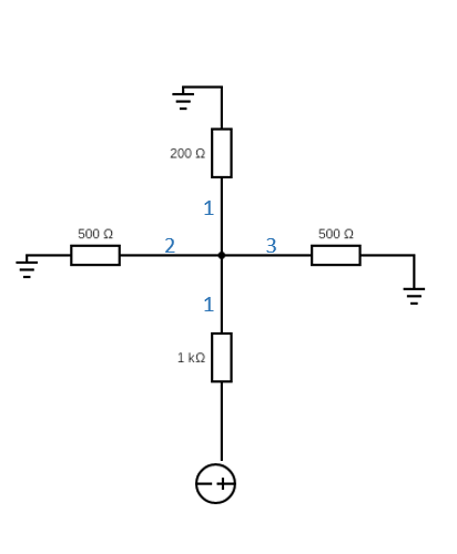
When you have a lot of junction dots in your circuit, it gets tricky to see what’s happening.
lots of junction dots

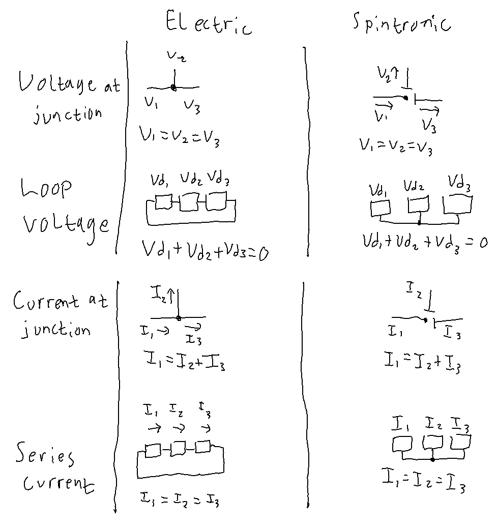
You have to trace the path of current through each junction, taking into account all of the junction dots. If it doesn’t pass by a dot, you must reverse the direction of the current, otherwise it stays the same. That makes it hard to just look at a circuit and see what’s happening. Is there a more digestible way to draw circuits that takes into account the current reversal at junctions?

Situation 3:

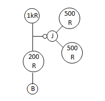
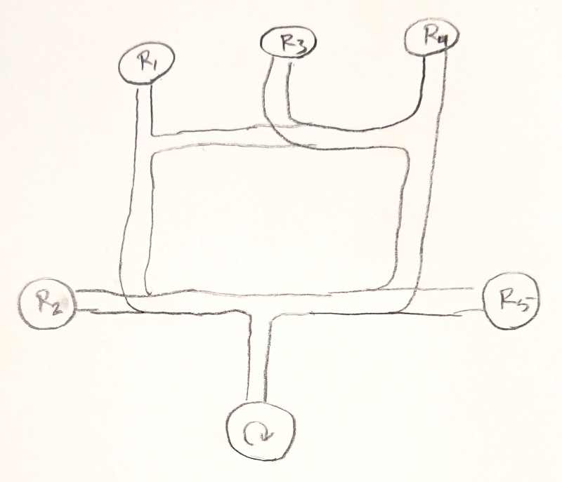
Spintronic junctions are a little more complicated than a single dot on a circuit diagram. Just like spintronic resistors and capacitors have two ‘terminals’ (i.e., where the chain enters and leaves the sprocket), each sprocket of a junction also has two terminals. Therefore, this symbol is not enough to fully describe a junction:

junction symbol

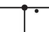
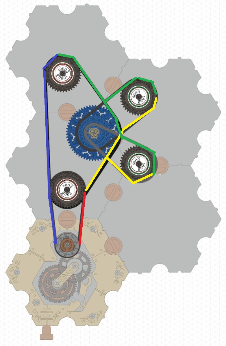
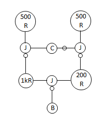
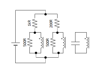
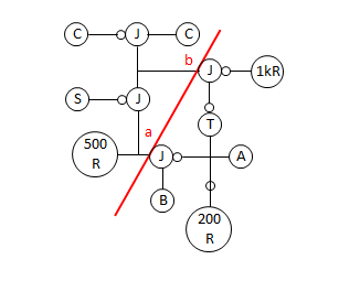
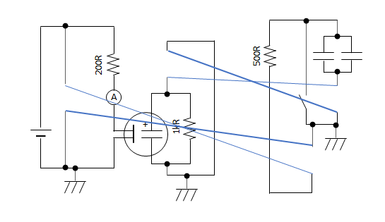
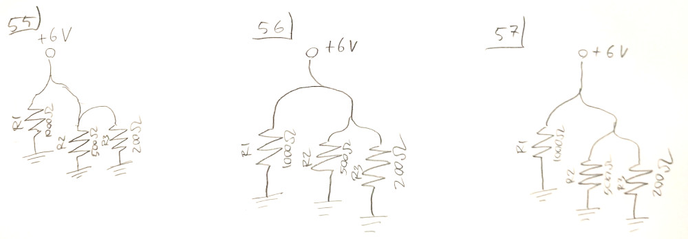
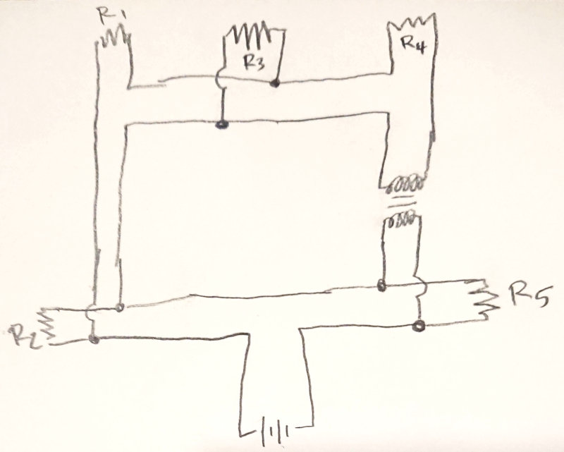
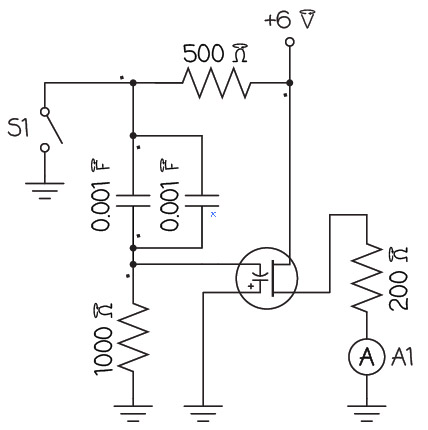
It only has three terminals! The other three terminals aren’t shown. But sometimes the other three terminals are necessary to draw. Like in this circuit:

image
https://simulator.spintronics.com?linkID=472

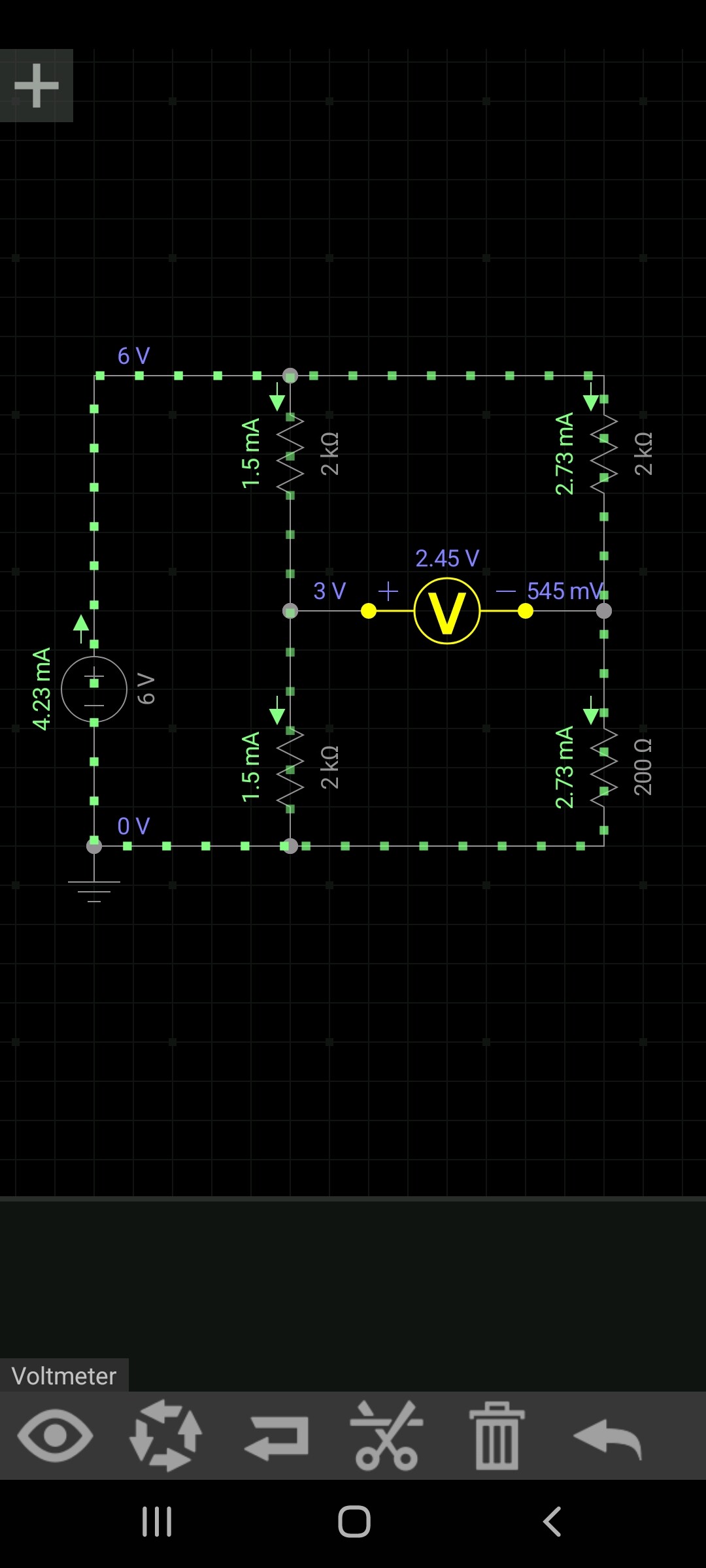
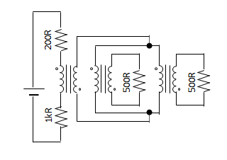
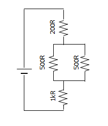
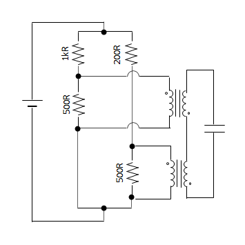
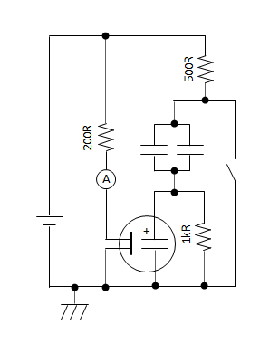
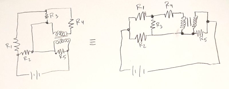
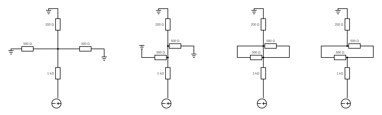
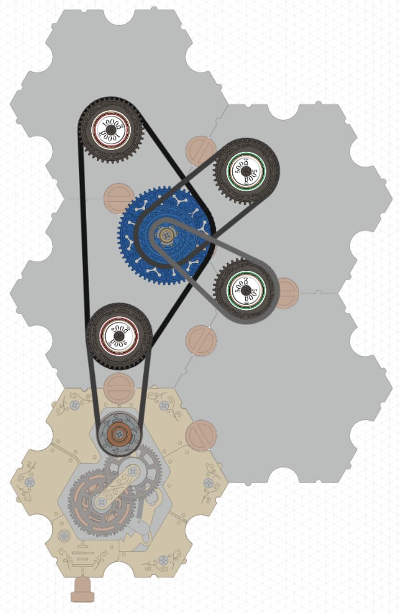
The circuit has a 200 Ω resistor, then two 500 Ω resistors in parallel, and then a 1000 Ω resistor in series. The traditional circuit diagram looks like this:

image

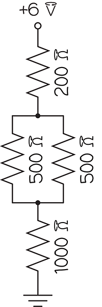
There are two junctions in the diagram, but in the spintronic circuit, there is only one junction part. That’s because the spintronic junction plays the role of both junctions in the circuit diagram. Drawn this way, you can see all 6 terminals.

Is there a better way to show that two junctions in a circuit diagram are actually the same spintronic part?

Summary

Is there a better way to draw diagrams for spintronic circuits that is easier to read and just works for any circuit?

1 Like

I don’t really know much about elektronics, I’m a bioscience engineer and had some theory in my physics course. For instance I don’t really know what a dot in the junctions mean.

What I remember from my physics course is that voltage between 2 points was the difference in the elektric potential in those points. Maybe it’s possible to visualise this potential with a colour gradiënt. The battery aways results in a 6V difference which needs to be covered, where always one side of the battery will be red, the other blue. Each resistor causes a colour change. I made an example, which might help see the diagram between the chains.

d47109d44e649321ec978acdd7d453ac7ff10b5e

I’m just wondering if this works for everything. Would these colours need to change dynamicly in oscillators?
In the example above, I’ve coloured the bottom resistor as being on the red-yellow line. But isn’t it partly resisting the blue line as well?

1 Like

The junction dots aren’t a thing in regular electronics, except that you see them on transformer symbols to indicate the direction the two sides are coupled to each other. In spintronics, you can couple in all sorts of other ways, so the dots become useful to indicate the direction of coupling on other parts. On junctions, the dots are used to indicate which direction the current will flow through them. Once you work through the book to that point, you’ll learn about the dots in the symbol for the junction.
I really like your idea of generating a color gradient that corresponds to the force on each section of the chain. That could be really helpful in the spintronics simulator. That’ll have to go into a future update for sure.
To answer your question, yeah, they’d change color with time in an oscillator. And I think the way you drew the colors on the image there are correct.
Thanks DobbelB!

Your original diagram is’t nessesarly incorect. I belive you just have your junction belts missplaced.
Screenshot_20221115-131523_EveryCircuit

A strategy to diagram mechanical action and logic consistent with electronics is to jump up the ladder-of-abstraction to a more general schema.

Several schemes come to mind- Feynman Diagrams, Petri Nets, Category Theory, and so on. As these are Turing Complete languages, they can subsume all multi-physics.

At the outset, I am basing this on information on the internet, as I do not have this kit. So it may be some misplaces.

Now, I have generally worked out my method of converting from a real arrangement to an electric circuit, and I will write it down.

Each component has the property of short-circuiting if nothing is connected to it.
This is more like a water hose than an electric wire.
To stop the current, it is necessary to connect an OFF switch with high resistance, like a plug in a hose.
11

When chaining components together, we should write it with a virtual transformer.
It is more accurate than connecting them in series.
This is because the voltage is a potential, whereas the force on the gear is a vector of differences.
12

In most cases, transformer coupling can be converted directly to series.
The junction corresponds to the following circuit.
13

Here, the circled mark represents the largest gear.
The junction is estimated to have the following equation for planetary gears.
rw1 = rw2 + rw3
The velocity rw corresponds to the spin current and the force F to the spin voltage.
In converting to an electric circuit, it seems important to have only one gear with a different orientation in the formula.

Based on this, the third example is converted into a circuit.
The diagram was simplified and written as follows.
14

I write it with transformers.
15

The left loop is physically a node corresponding to a component that turns in sync with the battery.
Each transformer can be converted directly into series.
16

On the way, the order of the 1kR, 200R, and junction at the left node is arbitrary.
This corresponds to the fact that the V and I of the entire circuit remain the same even if the order of each component is swapped.

Next, consider the first pattern.
21

The chain is inverted between the capacitor and the joint, which is represented here by a circle on the line.
When writing the circuit, the area near the capacitor is divided by a transformer.
22

Here, a capacitor is placed in series on the 1kR side.
This raises the question of where to install a new transformer to couple with the 200R side.

We try to place a transformer on top of the capacitor.
23

In this case, the problem arises that the potentials of the connecting lines cannot be matched.
In other words, the circuit diagram cannot be simplified any further.

Next, we consider placing a transformer under the capacitor.
24

Circuits can be made in series because they have the same potential on the ground side.
25

Incidentally, consider an example of failure, the case of not reversing the direction of the chain on the right.
The schematic, divided by the transformer, is shown below.
26

This can be rewritten as follows.
27

Since the voltage corresponding to the capacitor is the sum of the 200R and 500R voltages, it is necessary to float the capacitor side potential in this way.

I will try to convert the second example.
I wrote the diagram referring to the Pulse Generator on the top page.
31

When making the schematic, I divide it into two parts at the junction here.
32

Write the right side.
33

The left side looks like this.
If the connection of the components is simple, as in the capacitor location, the orientation of the junction does not matter.
34

In the schematic above, GND is added by hand to match the transformer location.
Combine these and attempt to remove the transformer.
35
36
37

The position of 200R is different from the sample circuit.
However, the circuit functions are equivalent and should be indistinguishable when converted to an electric circuit.

Whether this method will work in other circuits, the details of transformer orientation, and the reverse transformation from electrical circuit to spin component placement will need to be considered in the future.

I thought about this for a while, and I think a good way would be to use lines to represent groups of coupled chains. This turns the usual convention of circuit schematics on its head, because a net now represents matching current rather than matching voltage, and voltage “flows” like current normally would along lines. Here are my schematics for each of the components:

Spintronics - page 1

I wanted to also put a picture of the voltage and current laws and some example circuits, but it seems like there’s a restriction on how many images I can post at once.

1 Like

It seems like my new user restriction has gone away, so here’s the rest of my diagrams.

Here are the voltage and current laws for spintronic diagrams. Notice how voltage needs a direction to make sense with junctions, while current no longer needs a direction (since there’s only clockwise and counterclockwise current).

Spintronics - page 2

Here are some example circuits using spintronic diagrams. (The component with a curved arrow is a diode.)

Spintronics - page 3

2 Likes

I’m really loving the suggestions above. @Yama-chan 's suggestion to diagram with transformers is obviously the overall correct thing, if somewhat long-winded. It also has the advantage that it would easily adapt to the obvious missing Spintronics part, namely the standard clockwork thing of a resistor or switch with gears of different sizes, like if you froze the satellite gears on the junction. That obviously functions like a transformer. One tweak I’d make to those pictures is that single parts (except for the junction) actually have three transformers in series, corresponding to the three different levels of gears.

I also like @ishanpm 's shortened diagrams, though I haven’t fully absorbed everything.

I do have one suggestion for drawing the junctions, improving over the dots decorating either @pgboswell 's printed drawings, @Yama-chan 's transformers, or the bars in @ishanpm 's drawings, and that is to draw them like a train track:
train-track

This way it becomes really easy to track visually whether circulation direction is reversed: if you make a sharp turn, it gets reversed, otherwise not. For instance, I would diagram Challenges 55–57 like so:
challenges
I find it much easier to read off the reversals this way.

These train tracks come from diagrams I use as a mathematician studying topology. There are other diagram techniques that come up there, namely the concept of fat graphs. (I would describe them a little differently than that Wikipedia link.) I haven’t figured out exactly how to use those, but I think those techniques will end up being useful.

1 Like

I’ve been thinking about this question, I think there’s actually a lot to say. The TL;DR is that spintronic and electronic circuits are very similar, but differ in practical issues that push opposite ways:

  • Spintronics chains are, well, chains, and when diagramming a spintronic circuit it’s natural to pair up your “wires” into pairs that have the same current. This pairing behaviour is automatic for any electronic circuit that is series-parallel decomposable, but for more general circuits you need to use various tricks.
  • A spintronic transformer is trivial to create and virtually perfect, unlike electronic transformers which are large, bulky, and leaky. Indeed, you need (effectively) transformers to create general circuits, as @Yama-chan explained.

For the second point, the provided parts most easily allow only 1:1 “transformers”, but that makes surprisingly little difference; for instance it’s easy to create a 2:1 transformer by effectively the standard electronics trick of running through the transformer twice.

I have more thoughts about how to diagram and work with these circuits, but here I’ll just show the diagrams that I’ve been drawing for myself. These are very similar to the ones @Yama-chan and @ishanpm drew, except that I’m explicitly doubling the wires. Here, for instance, is a spintronics circuit modelling the simplest electronic circuit that is not series-parallel decomposable:
spintronics-circuit
Here is a simulator circuit (with some extra voltmeters for verification) and it models this electronic circuit as discussed in another thread:
electronic-circuit
By comparison with the pictures suggested by @Yama-chan and @ishanpm, I’m explicitly doubling the wires (in the fat-graph way), and drawing the junctions in the train-track way I suggested above. I’m also thinking of a “loop” going as its own component (going through multiple other components) and drawing them explicitly, although I didn’t circle them. This is quite close to how the circuit is actually constructed, omitting some practical details like which level the chains are on.

We can solve a circuit in this layout by recording the current and voltage (tension) difference on each segment:
spintronics-analysis
The numbers on each edge are Voltage/Current. I divided the resistance to make it easier to write. But you can verify, for instance, that the voltage in the simulator across one of the 2000 Ohm resistor is 22/31*6 V.

In a reverse of the situation for electronic circuits, the current does not depend on the direction you are looking at the two pieces of chain: they are either circulating clockwise or counterclockwise, i.e., like British or American drivers, respectively. But the voltage does depend on the directionality: to get a positive voltage flowing out from a battery, you take the tension on the right chain segment minus that on the left chain segment.

The result looks very similar to an electronic circuit, but it is not. Instead, to get an equivalent electronic circuit, you need to “break” every loop and insert a 1:1 transformer:
04-conversion
This circuit can be redrawn to see that there is a connection running directly across the transformer, which can then be simplified away:
05-simplification

I’m pretty happy overall with these diagrams, they seem to be easy to work with for planning.

3 Likes

To be honest I do find the use of a dot to indicate the Level 1 connection a bit ambiguous. For 3 reasons:
1\ dots are also used for the junction itself. I would prefer a different symbol to avoid confusion.
2\ at the scale printed the dot floats around the L1 connecting wire. I think it would be clearer if it was closer the wire.
3\ it only indicates the L1 connection. But for the remaining L2 and L3 connections there are two possibilities for connection.

I would recommend instead using numbers next to the wire. You only need to specify two of them to describe the connection unambiguously.

01 circuit level markings

Then the user can follow the rotations from battery upwards, perhaps sketching out the rotations as they go as below in red. Also, I think drawing the circuit with the battery at the bottom makes it easier to follow. I’m one of those who must rotate a roadmap in the direction I’m driving!

02 follow arrows

I am also not a big fan of closed loop circuits. I prefer a point DC source and all branches eventually going to earth to close the loop instead.

When the switch is used as a current source it could also be represented with an S inside a circle as below instead of an open switch which needs two terminals. A level changer could also be used as a source perhaps using an L symbol.

Retrograde Motions

Retrograde motions could be indicated by a minus symbol before the level marking. eg. -1 instead of 1 would indicate that connection is to level 1 but the other side of the sprocket. Direction of rotation is thereby reversed ie. CW to CCW or CCW to CW. Following the chain further from S1 to C1 one encounters another -1 which reverses the chain direction again back to the original direction.

03 reverse coupling

When connecting a 2nd component to the resistor on a different level, the 2nd component takes on the direction of the 1st resistor. You can confirm this by following the current path from the S1 to the R1 then onwards to R2. Here it encounters a -1, but no 2nd -1, so the rotation remains reversed down to R2.

04 reverse ocupling adv full

This avoids the use of loop circuits with dashed lines and even more dots that indicate inverse coupling. I find that sort of sketch cumbersome to follow.

Double Connections

On a similar note, I think double connections to a junction, as in eg. a V doubler or halver, could be represented by a double line similar to a double bond in Chemistry. In this case only one level needs to be specified for an unambiguous connection diagram. The following somewhat convoluted loop circuit diagram then reduces to this.

double bond 2

4 way Junctions

I see this circuit from gut feel as a 4-way junction. The 200, Junction and 1K resistor are in series from bottom to top (as indicated by both sharing the “1” label) and the 2x500 resistors either side on L2 and L3 (pic 1).

circuit 4 way with labels

Somewhere in the Act One text it is mentioned to sketch first your gut feel. Then if it contains eg. a 4 way junction it can be split into two 3-way junctions in series (pic 2).

circuit 4 way 2

The earth already captures the fact that the return chain goes back to the junction and eventually the battery. They could also equally well be depicted as returning to the junction. Since the junction is split into two virtual junctions, they can return to the other terminal in the diagram, it’s the same physical junction (pic 3).
By the same token there is no physical connection between the two virtual junctions. They are the same junction. So, the “wire” connecting them also disappears (pic 4). So, the two depictions pic 1 and pic 4 are equivalent.
But as far as sketching it for a Spintronics build So I would just sketch it as a 4-way junction with markers to indicate the levels. The two L1’s make it clear the spine of this circuit is in series and connected with a single chain. Connections are clear and the rotations are easy to follow.
In real circuits I guess 4-way junctions are possible and probably occur all the time. So being as close to as possible to real life circuits is also a bonus.