Spintronics Community Forum

Checking my intuitions with Challenge 51

I did not succeed at Challenge 51 on my own. In retrospect, it seems like I got the right structure, but missed the specific details of which resistors go where (and, also, played with a lot of structures that didn’t work).

You can actually play with this one by just building this and pushing on the resistor in the upper right to stop it:

2022-12-12_18-40-15--IMG_20221212_1840151

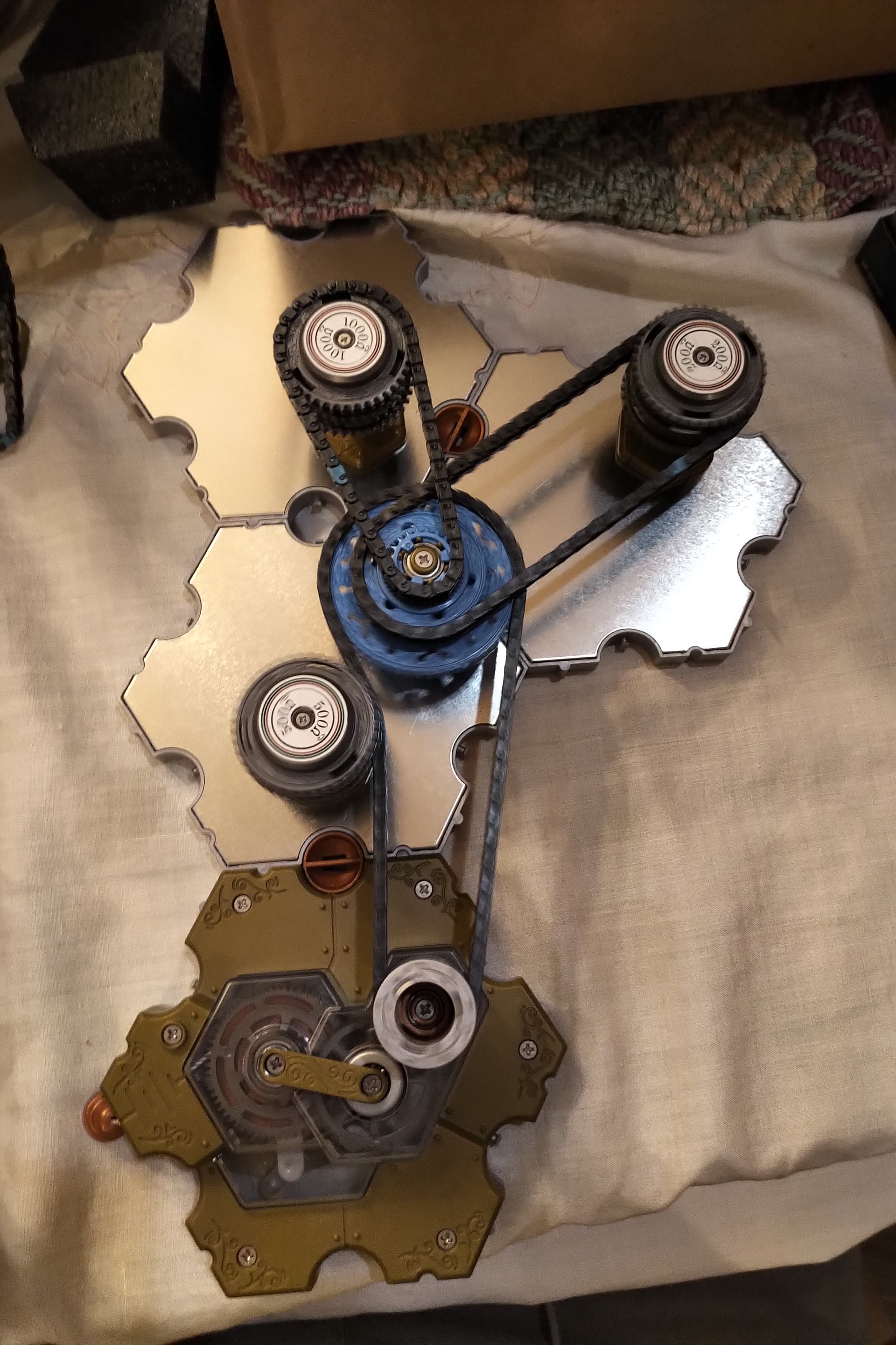
Doing so, I noticed that, in particular, removing the resistor between the battery and the junction, or the resistor that is/would be attached to the button, the effect doesn’t occur.

If anyone wants to explain it in more detail, I’d be super interested, but my sense of how it works is this:

The battery produces some large number of units of rotational speed (I’m making this up to express my intuition, don’t judge). For purposes of assigning numbers, let’s say it produces 20 rotons.

Cranking the 1000 Ohm resistor at max speed needs at least 8 rotons, and doing so will pass 2 rotons on to the next thing in series, if any. The 500 Ohm resistor is 5 and 5, the 200 is 2 and 8.

So if you have just the battery, a junction, the 1000 and the 200, they both run at their max speed; stopping the 200 doesn’t make the 1000 go faster because it was already going as fast as it can, and vice versa.

If you put the 500 in the way before the junction, there’s only 5 rotons to split between the 200 and the 1000, so they both go pretty slow. If you stop the 200, all 5 rotons go to the 1000 and it noticeably speeds up (but still doesn’t reach its max speed).

Is that … loosely correct?

I’m in a similar boat… I eventually landed on a “solution” that didn’t match the book, but it was late, and in the morning I realized I had the opposite (and much easier) effect of more amps when the button is pressed.

After some tinkering, some Googling, and some math, and many fixes to my bad math, I think I’ve figured out how the intended solution works. It all has to do with the topics covered in Tutorials 14 and 15. In the spirit of Spintronics, I’ll try to use as little actual math as possible…

So when the button is off, it’s effectively a series circuit. There’s 1500 Ohms of resistance total, and 500 Ohms of it are before the junction. That means, that, proportionally, the junction feels 2/3 of the total voltage. And of course, a lower voltage means less current combined with the 1000 Ohm resistor in series with the ammeter. (the current comes out to about 4 milli-spin-amps if you do the calculations)

When the button is on, things get interesting! We now have two resistors in parallel; a 1000-Ohm and 200-Ohm. You might have noticed by now that two parallel resistors combine to have less resistance than either individual resistor. The exact formula isn’t super important for the explanation, but it works out to about 167 spin-ohms, so the whole circuit now has 667 spin-ohms of resistance.

So here’s the trick: the proportion of resistance, and by extension voltage, has now changed, too! With the button off, 33% of the voltage was “used” by the time we get to the junction, but now with the button on, roughly 75% of the voltage has been used up! (If you look again at Tutorial 15, you can imagine we have a 500-ohm and 167-ohm resistor in series) So now with less voltage available, the current to the ammeter drops as well (to about 1.5 milli-spin-amps).

The reason that the resistor between the battery and the junction is key to this is that without it, there’s no proportions to mess with by changing the resistance of the junction. That is, without the first resistor, both junction paths would get the full 6 spin-volts regardless of how much resistance was in either path.

So by turning a switch on, we drop the resistance of the junction, which causes the voltage drop of the first series resistor to increase dramatically!

It’s definitely a weird thing and I’m not surprised the book avoided trying to explain it :slight_smile: